WN9 Software for Spline Shaft Connections to DIN ISO 14
WN9 is a new software for calculation of spline shaft connections with straight flanks.

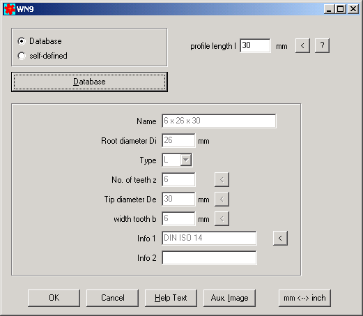
Standard dimensions according to DIN ISO 14, DIN 5471, DIN 5472 and DIN 5464 may be selected from integrated database, or you can calculate any self-defined spline shaft profile.
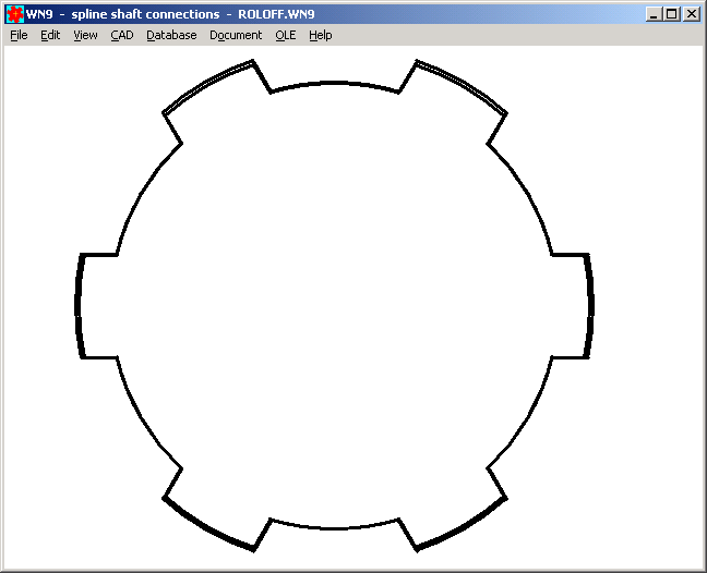
ISO tolerances for sliding fit, transition fit and press fit can be suggested by WN9, or you can enter any ISO tolerance. Tooth profile can be generated as true-scale drawing and exported to CAD as DXF or IGES file.
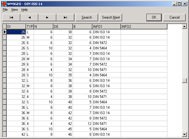
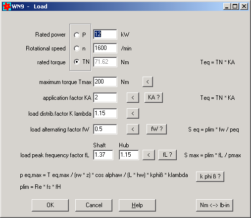
WN9 includes calculation of load capacity according to Niemann Machine Elements 1 (2005). Material data can be seleceted from integrated material database. For input of application factor, load distribution factor, load alternating factor and peak load factor, WN9 suggests values or provides auxiliary pictures.
Price of WN9 is 170 Euros.
FED1+ Preview
Spring travel, shear stresses, safety coefficients and life expectation have been added to FED1+ Preview table (34 columns now).

Variant Calculation by means of Preview Function
Preview function is also applicable to compare variant calculations and to choose the optimal machine element. For variant calculation, first create a new folder (at "File->Save As"). Then calculate and save the variants with different file names in this folder. Simply use preview function at "File->Open Table" to compare the results. You can use menu option "File->Export Excel" to start Microsoft Excel (if installed) with the preview table as worksheet.
FED2 Max. Spring Length at Dynamic Load
The (non-standard) signs Lkn, skn, Fkn were used for permissible spring length, permissible spring travel, and permissible spring load in case of dynamic load (shear stress taukn = tau perm). Because of danger of confusion with length of spring body Lk, signs have been renamed into Lnk, snk, Fnk.
FED3+ Load-Path-Diagram with Tolerance Zones
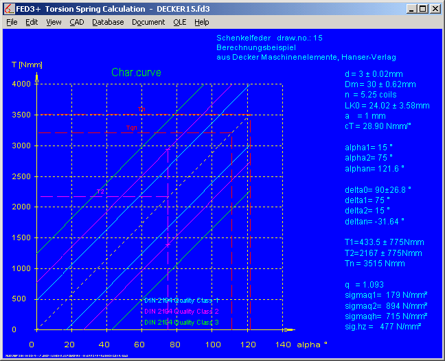
Characteristic line of spring can now be drawn with or without tolerance zones to grade 1, 2 and 3 according to DIN 2194.
FED3 Permissible Bending Stress Sigma b perm = 0.7 x Rm ?
According to EN 13906-1, permissible shear stress tauz of compression springs is calculated from tensile strength Rm: tauz = 0.56 Rm. For extension springs, tauz = 0.45 Rm according to EN 13906-2. It seems, that lower coefficient should compensate additional bending stress in the transition zone spring body spring loop.
Torsion springs are loaded by bending, not by torsion. Permissible bending stress sigma b perm is defined in EN 13906-3: Sigma perm = 0.7 Rm. Why 0.7 ? Compared with material data of similar materials, permissible bending stress (static) is equal or even higher than tensile strength. How is relation to permissible shear stress ? We calculate Sigma b perm / tau perm = 0.70 Rm / 0.56 Rm = 1.25. This seems strange, according to Mohrs circle bending stresses are double value than shear stresses.
If Sigma b perm = 1.0 Rm, Sigma b perm / tau perm = 1.0 / 0.56 = 1.78.
It seems, that torsion spring calculations according to EN 13906-3 are too conservative. The life time of torsion springs should be much longer than calculated by FED3+ (with Sigmab/Rm=0.7).
If you made endurance tests with torsion springs, please let us now the results to compare the calculated life expectation with the real life time.
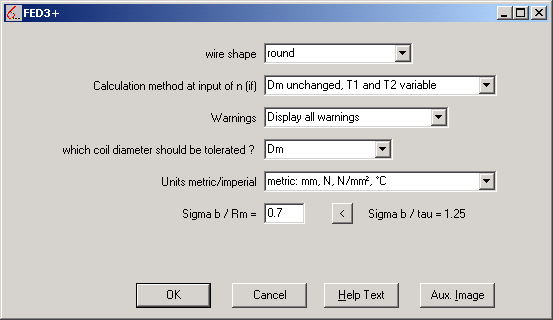
In the new version of FED3+, you can modify the coefficient Sigma b perm / Rm. Changing the standard value of 0.7 is reported by a warning "Sig.b/Rm <> 0.7 (EN 13906-3)".
FED6 Statistical Calculation of Rejects
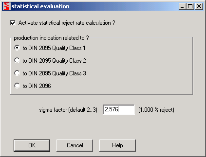
Like in FED1+ and FED2+, FED6 now calculates reject rate for self-defined small tolerances. At "Edit -> Statistics" you have to enter the average reject rate for production to a defined quality class. This mainly depends on the machine where the springs are produced, i.e. reject rate may be 1% for tolerances to DIN 2095 quality class 1. Then select quality class 1 and enter Sigma = 2.576.
SR1 F pre
F pre was introduced as alternative to preload FApre. F pre is a constant axial force between bolt head and nut thread. F pre increases required assembly preload. Different from FApre, Fpre does not increase tightening torque (by friction load FApre/µK).
Fpre and FApre are used to consider preload of clamping plates (i.e. bolted joints on automobile-body C sheets).
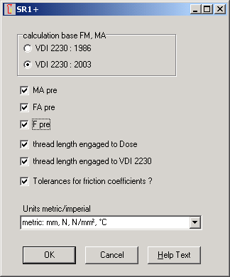
SR1 MA pre, FA pre, F pre on Demand
Preload forces and preload torque is not part of VDI 2230. To avoid queries ("where are Fpre, FApre and MApre described in VDI 2230?"), input fields and calculation of these special loads can now be enabled at "Edit->Calculation Method". In standard settings, MApre, FApre and Fpre are disabled now.
SR1 FA pre and F pre on Eccentric Applications
FApre and Fpre are now considered on eccentric joints and loads as well (FA replaced by sum FA + FApre + Fpre).
SR1 MA pre
For self-locking screws and self-tapping screws you can define torque MApre caused by thread friction. MApre increases tightening torque MA, but on the other side it also reduces maximum tightening torque because of higher torsion stress. Influence to reference stress was not considered in earlier versions of SR1.
SR1 Fatigue Stress
New version of SR1 considers changes in VDI 2230:2003 on fatigue strength calculation. Dependent on selection at "Calculation Method", fatigue strength is calculated to VDI 2230:1986 or VDI 2230:2003. The result for safety SD is almost the same, whether old or new formulas are used.
SR1 Equivalent Diameter
Equivalent diameter dequ of bending body was limited to outside diameter of clamping plate for the case dequ > da.
SR1 FA Curve in Load-Extension Diagram
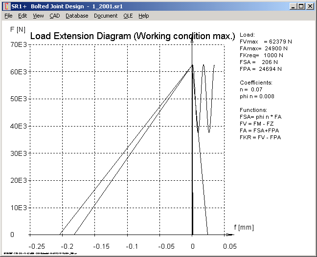
To emphasize axial force FA, a symbolic sine wave has been added to the load-extension diagrams
(for pulsating load with FAu=0).
SR1 Screw Head Databases
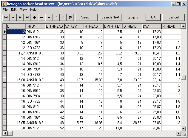
New standards and dimensions have been added to the databases for hexagon socket head screws and for hex flange screws:
Hexagon socket head screws
ISO 4762: replaces DIN 912 (almost identical)
DIN 6912: hexagon socket head cap screw with center, low head
DIN 7984: hexagon socket head cap screw with low head
Hexagon flange screws
EN 1662 (small series)
EN 1662 is almost identical with IFI 536. Only M12 differs: EN flat width 16mm, IFI 15 mm.
EN 1665 (heavy series)
DIN 6921 was replaced by EN 1665. Larger flat width for M10, M12, M14, M16, M20.
WST1 Preview: Quick View Graphic
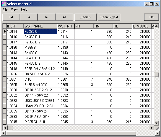
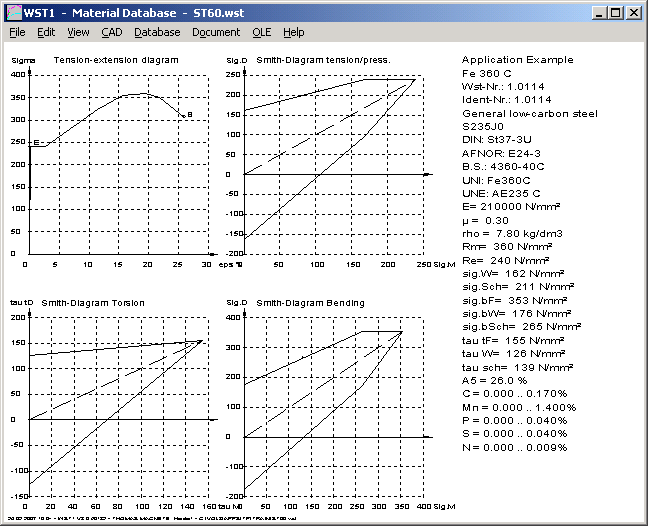
Quick View with stress-strain diagram and Smith diagrams is now displayed in the background when you click into a material in the table or use cursor keys to select next/previous material at "Edit-Preview". Now you can see immediately, if fatigue diagrams are available for the desired material or not.
WST1 Material Data
Strength values have been added for 1.0603 (C67). Shear stress tau sch of 1.7103 was changed from 590 to 490 N/mm².
WN1 Dimensioning p, T, Fax
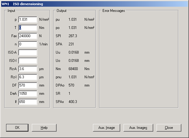
When use Dimensioning window of WN1 to calculate a press fit, you can input either required pressure p or transferable torque T and axial load Fax. At input of Fax and T, WN1 calculates equivalent pressure p. If you change T or Fax, p is recalculated. If you change p, T and Fax are recalculated.
In case of low pressure but very high Fax and T, rounding error occurred (p=1,031 recalculated and changed Fax=240000 into 240009 without input). Initial field at Dimensioning window was set from pressure p to torque T to avoid this error.
ZAR1+, ZAR2, ZAR6, WL1+: EDI-Export/Import
EDI files are used for export and import of files between calculation programs. "File->EDI Menu" was changed to "EDI Export" and "EDI Import" at File menu.
ZAR1+, ZAR3+ Tooth Contact Drawing: Pitch Circle and Operating Pitch Circle added
Pitch circle diameters d1 and d2 and operating pitch diameters dw1 and dw2 have been added to the tooth contact drawing. If sum of profile shift coefficients x1 + x2 = 0, pitch circles touch tangential in tooth contact point, pitch circle and operating pitch circle are identical. If x1 + x2 <> 0, operating pitch circles dw1+dw2 touch in tooth contact point. Operating pitch diameter dw depends on counter wheel, pitch diameter d not. A planet wheel may mesh with sun gear on another operating pitch diameter than with ring gear.
ZAR3+ Animations
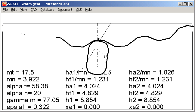
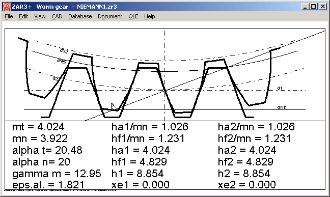
Plus-Version of ZAR3 includes now animations of tooth contact between worm and worm gear (axial and radial sectional view).
