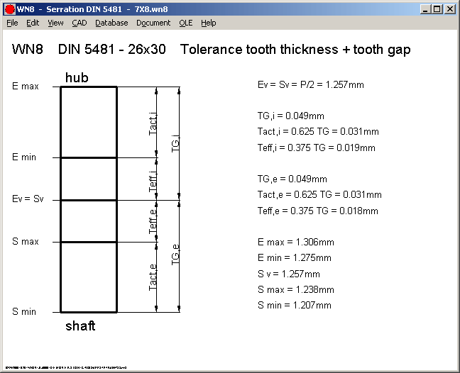
DIN 5481 includes many tables with dimensions (min, max, nom), measuring dimensions and form diameters. But no formulas and no standardized tolerance system. Tolerance fit system tooth thickness / tooth gap is described in DIN 5481 with TG, T actual and T effective. But to get these basic tolerances, you must calculate it from the tables with tooth dimensions Sv, Smax, Smin, or from tooth gap dimensions Ev, Emax, Emin.

WN8 generates a screen graphic with tolerance system tooth thickness / tooth gap together with the values of the selected serration spline.
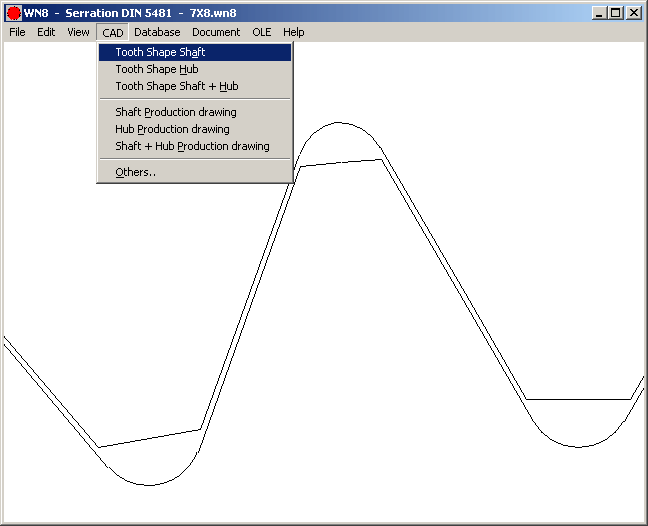
WN8 generates a true-scale tooth drawing of external and internal spline, that may be loaded into CAD as DXF or IGES file.
WN5 - Involute Splines according to ISO 4156
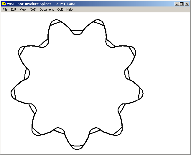
A new ISO 4156 standard for metric involute splines was released in October 2005. The ISO 4156 involute splines are identical with ANSI B92.2-1980 and can be calculated with our WN5 Software.
WL1+ Overlapping Stress Concentration Zones
If notch zones cross shaft shoulders or overlap with other notch zones, the product of the stress concentration factors (ß1 * ß2) is used for calculation of the peak stress. If you only want to consider the highest stress concentration factor of the overlapping notch zones, you must split the notch zones (until begin of other zone, start new zone after end of other zone).
WL1+ reports overlapping notch zones in the newest version.
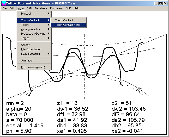
ZAR1+ Tooth Contact Graphic
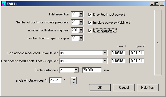
At "View-Tooth Contact" you can now choose between screen graphic with and w/o configuration window. New in the configuration window is an up/down button to change the rotation angle of the gear. Tooth contact graphic in the background is now immediately updated after modifications.
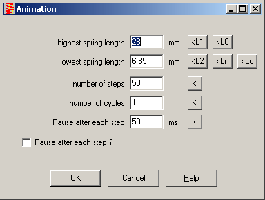
FED1+,2+,3+,6,7,12: Animation
Pause after each animation step in milliseconds may be set now in the input window for animation settings. Default values have been changed according to faster computers nowadays. And buttons for default spring length L0, L1, L2 and Lc (or spring angles in FED3+) have been added.
FED1+, FED5, FED6, FED7: View -> Drawing L = ?
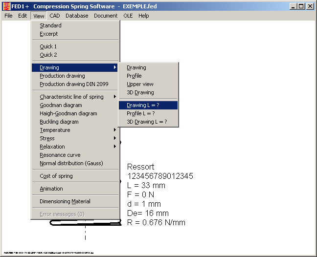
Spring drawing can be generated for any spring length between L0 and Lc. Until now, this option was available in CAD menu only.

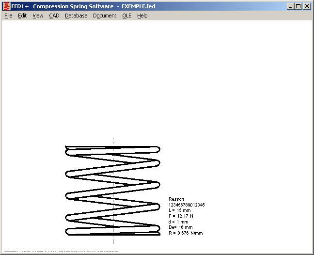
FED7 – Spring Length L1, L2, Lx
Initial value for L1, L2 and Lx is set to 0 now. To display a spring drawing or Quick View after input of spring sections, FED7 sets L1=0.9*L0, L2=0.8*L0, and Lx = (L1+L2)/2 for this case. Until now, for invalid values (L > L0 or L < Lc) spring could not be calculated and you first had to enter valid spring lengths.
FED6 - Printout
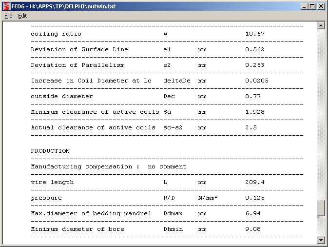
Coefficients of the spring calculation have been added to the printout. At printout of quality classes, a misprint was corrected: Tolerances according to DIN 2095, and not DIN 2097 (also in FED5 and FED7).
SR1 - Washers to DIN 6796
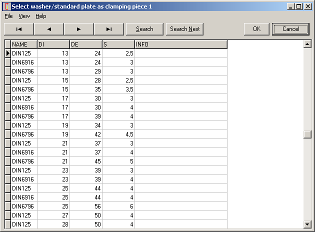
Washers according to DIN 6796 have been added into "klemmstk.dbf" database for clamping plates.
