
SR1 Bolt/Nut driven Tightening Procedure
For bolt/nut joints you can select if bolt or nut is driven. This affects tightening torque, mean friction diameter is calculated from hole diameter of the lowest clamping plate and dw of the nut. ľK is the friction coefficient of the nut surface for this case.

SR1 Clamping Plate Material Data
Because the combo box shows name and permissible pressure only, a new button has been added that shows clamping plate material database with all data.

SR1 Database field length
Info field length can be enlarged to user-defined length now with any database software. Furthermore, you can modify the field titles. If no database available, you can download the tool "WCREATE" from SSI-Software at www.hexagon.de/history/tools (do not use Excel for database modifications).
SR1 - Fv
FVmin/max = FMmin/max (assembly prestressing load) - FZ (settling amount) is the measurable prestressing force after tightening procedure without load. For FA=0 it is equal with residual clamping force FK.
FV=FM-FZ has been renamed to FVreq = FMmax,req - FZ
Bolt material A4-80 has been added. Thermal expansion coefficients of all austenititc steel (A4-80, A2-70, A2-50, A4-80) changed to 16,5E-6 1/K.
SR1 - MApre
For self-locking bolts and nuts, pre torque by friction must be considered. Tightening torque must be increased, or assembly prestressing load is reduced.

New VDI 2230 (October 2001)
New VDI 2230 was released now, we will add changes at next versions of SR1/SR1+. Because there seem to be some errors, you can select if SR1 calculates according to old or new VDI 2230.
Unfortunately, the improvement suggestions from GM and me were not considered. No minimum and nominal tightening torque will be calculated. FM was not renamed to FMmax, but to FMperm.
FMperm is an input value, or will be calculated as function of the nue coefficient. With nue=0.9 they defined a new term "FMTab", that means the value you can select from the VDI table (if you have no program to calculate it).
At section 5.5.1, FMperm defines no limit, there is a "range of FMperm", starting from FMperm,min = FMmax,req and ending with 1.4*FMTab. That means, that yield point may be overridden by 25% during tightening procedure ?
Puzzling, that new calculation of required clamping force radial load: FKQ = FQ / (qF*ľT) (page 10) with qF = number of mating surfaces. Required clamping force becomes smaller for increasing number of mating surfaces.
Anyhow, Sigma redB is calculated now with the correct section modulus Wp=pi/16*dł, instead of the "corrected Wp" pi/12*dł from the VDI 2230 draft.
FED1+, FED2+ : Resonance Frequency for External Mass
If you enter an external mass at "Edit->Application", program calculates resonance frequency and amplitude of the spring-mass-system. A separate page with this data has been added to the printout.

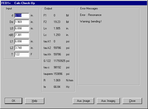
FED1+ Input of inches, lbf, psi
Input and output of data can be switched between Metric and Imperial units.
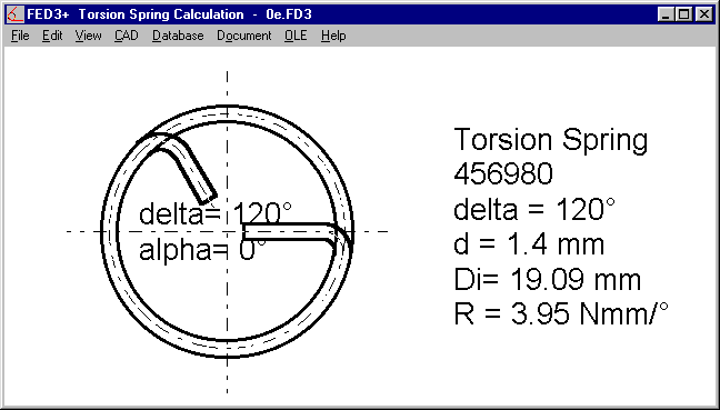
FED3+ Legs bent inside
FED4 Input Window
Input of Material data, production and application data has been split into 3 menu positions.
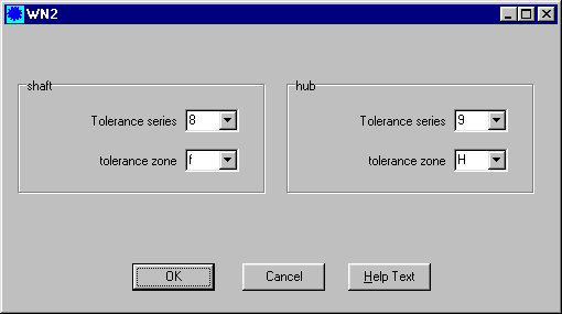
Input of tolerance series and tolerance zones was integrated to one window.
At tooth contact drawing, outside diameter of ring gear was influenced by changes of tooth root radius. Apart from that, specific sliding values zeta for ring gears had to be corrected.
Online Input: Calculation with Cursor Keys
Using cursor keys to enter next input field executes new calculation of the machine element now. If you want to execute calculation with OK or Enter key only, use Tab key or mouse to enter next input field.
Modification Info Info Field enlarged
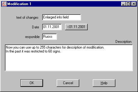
At "Document-Modification New" the description field was enlarged from 60 to 255 chars.
Configuration Dialog Window Size
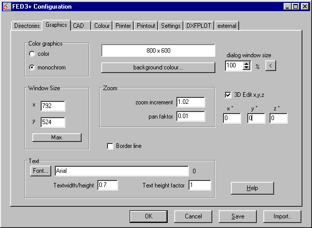
If you select "Large Fonts" at Windows settings, you must adapt the dialogue window size at "File->Settings->Graphics". Click to "<" button to get an appropriate value.
PDF files from Drawings and Diagrams
To get a file in pdf format, you first must print a postscript file, then convert the ps file to pdf by means of the Acrobat Distiller (according to Adobe, the founders of pdf format).
But I found a better solution:PDF printer driver: Send Drawings by Email
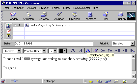
At www.pdfmailer.com a software tool "Pdfmailer" is offered, that (similar than a fax driver) converts any printout to a pdf file and sends it as email attached file.
After installation, at "File->Print" select "Pdfmailer" as printer.
Pdfmailer requires an Email program (Microsoft Outlook or Netscape Communicator) be installed on your computer.
TIFF Printer Driver
If you have to file drawings and diagrams as tiff files by a document management system: H&P Eurosoft offers a printer driver "directCONVERT NT" for Windows, which converts printout, drawings and diagrams to TIFF-G4 Format.
Website: www.h-p-eurosoft.de
Email: info@h-p.un.uunet.de
Pricelist | Order | Update Order | E-Mail | Homepage