English Deutsch
GEO4 Demo
A demo version of the new GEO4 software for calculation of cams and cam disks is available now, ready for download at "http.//www.hexagon.de/zip/geo4_e32.zip".
FED9 - Dimensioning
If you enter 0 for width and height of flat material or outside radius Re, FED9 calculates minimum value. Thanks to Mr. Füssmann for this suggestion.
FED9 - Spiral springs of circular wire
Until now FED9 was made for spiral springs of flat steel only. Now you can switch between flat steel and round wire. Thanks to Mr. Salm of Brand Springs for his suggestion.
ZAR1+ Single contact factor ZB
For pinions with z<20, ZAR1 may consider higher pressure at the point of single contact by means of the single contact factor ZB. Until now, ZB was considered then for gear 1 and gear 2. According to DIN 3990, ZB is considered only for the pinion, with the result of different Hertzian pressure for gear 1 and gear 2.
ZAR1+ Life expectation
For calculation of lifetime (if SH<1 or SF<1), the number of tooth contacts per revolution had not been considered, this was changed with the new version. Thanks to Pedro di Donato of Carraro S.A., Haedo/Argentina.

ZAR1+ Roughness flank/tooth root
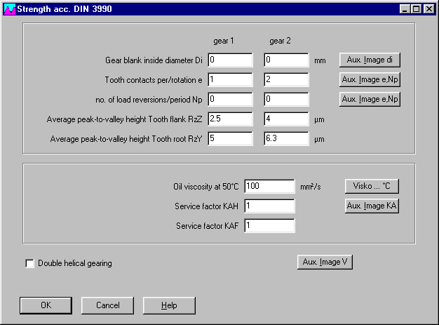
You may use different values for peak-to-valley height of flank and tooth root for gear 1 and 2. For gears with grounded tooth flanks, roughness of the (milled) tooth root is used for calculation of the safety against tooth root fracture (factor YrrelT), and the roughness of the grinded tooth flank is used for calculating tooth flank pressure (factor ZR). The average value of RzZ1 and RzZ2 is used for calculation of ZR. The factor Yrrelt may be different for gear 1 and gear 2. Thanks to Mr. van Vliet, Tech. Adviesbureau Schoonhoven/Netherland, for his improvement suggestions.
ZAR1+ Tooth thickness of outside diameter for chamfer tools
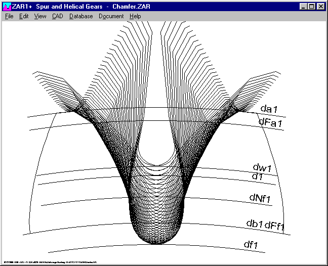
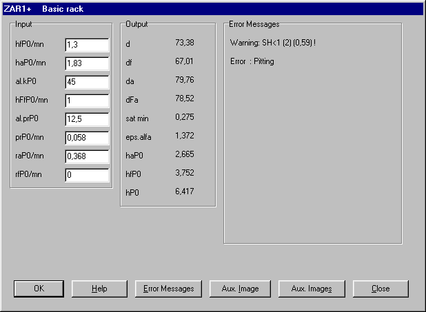
In older ZAR1 versions, tooth thickness san and sat were calculated at for usable diameter dFa, instead for ouside diameter da. With newer versions, the reduction of the tooth thickness by the tool chamfer at outside diameter is considered now. At online input of tooth profile, sat min is displayed now (instead of sat theor.). Thanks to Mr. Facciolla of CIP-Cia Indl Pecas, Guarulhos, Brazil, for his tip.
FED1+,2+,3+,5,6 - Production Drawing
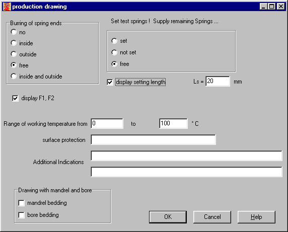
With the new versions of FED1, FED5 and FED6 you can choose, if settling length value should be printed withe the drawing, even if spring is not to be set (setting length used for test springs only).
Another new option is the production drawing without spring loads F1 and F2 (if application is unknown).
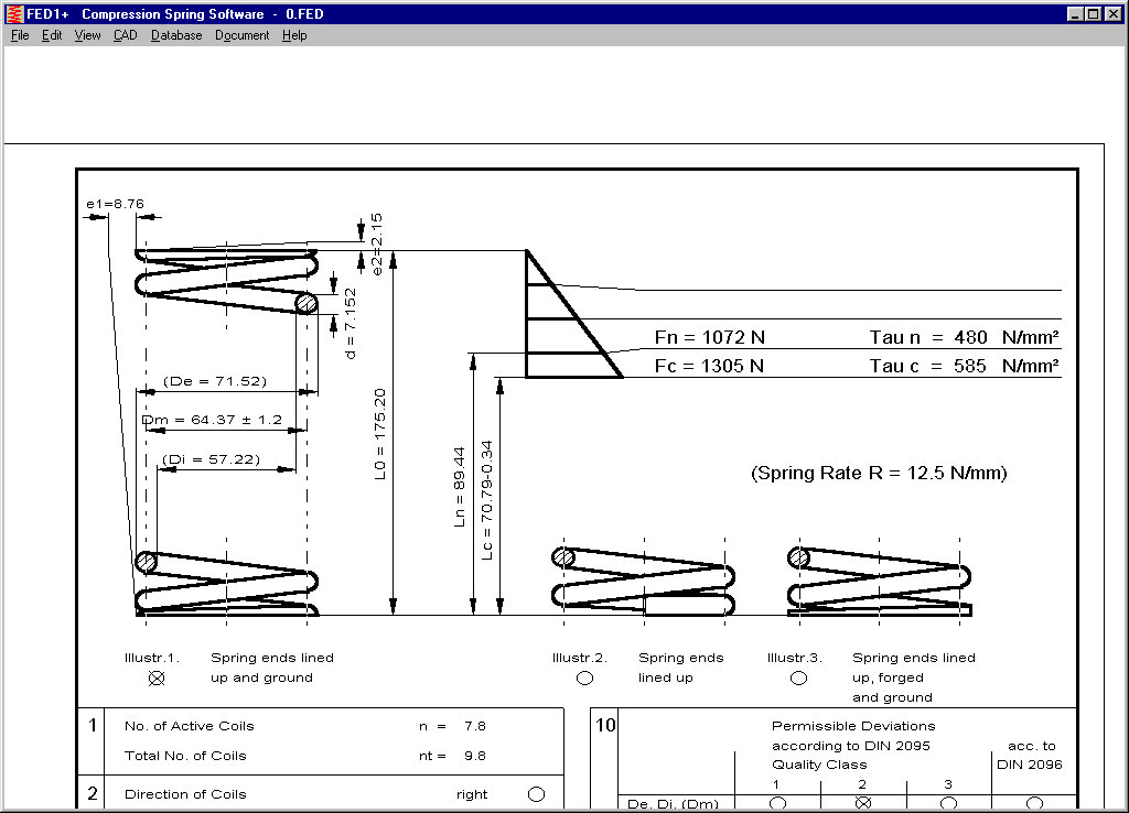
FED1+ prints value R/Dm as pressure for grinding of the spring. Grinding of springs with R/Dm less thans 0.03 N/mm² is difficult, FED1+ generates a new warning for this case. Thanks to Mr. Dietz of Federn-Dietz, Neustadt.
FED2+ Square, rectangular and elliptic wire for tension springs
As known from FED1+ and FED3+, the FED2+ software for extension springs is also able now to calculate springs of square wire. Rectangular and elliptic wire may be seldom for tension spring, but with the new FED2+ it is possible, too. (Plus version only)
GEO3 - Material database
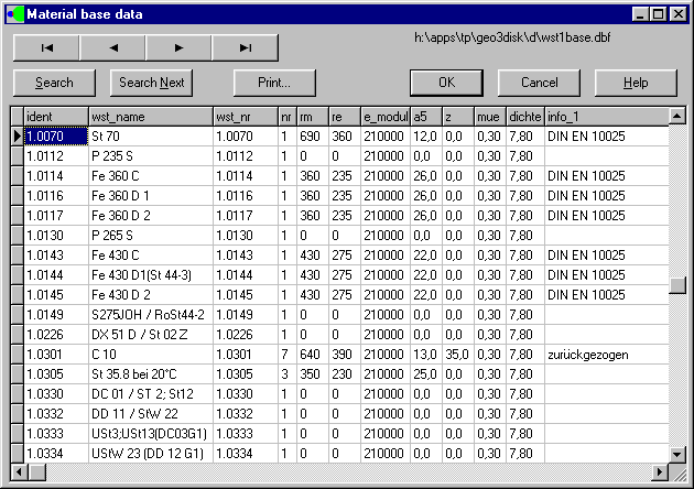
Many extensions have been added to the GEO3 software for calculation of Hertzian pressure. The permissible pressure of the material is considered now with 1.66*Re (yield point), GEO3 generates an an error message. If overridden. The material databse was extended, now all material base data of WST1 are available.
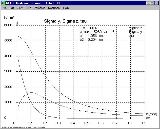
GEO3 - stress spectrum below contact surface
A new diagram shows the curves of axial stress and shear stress as function of depth from contact surface. This diagram may be useful when determining the required hardness penetration depth of the contact body.
GEO3 - Table Drawing
A drawing with the contact bodies together with the essential results can be printed as table drawing.
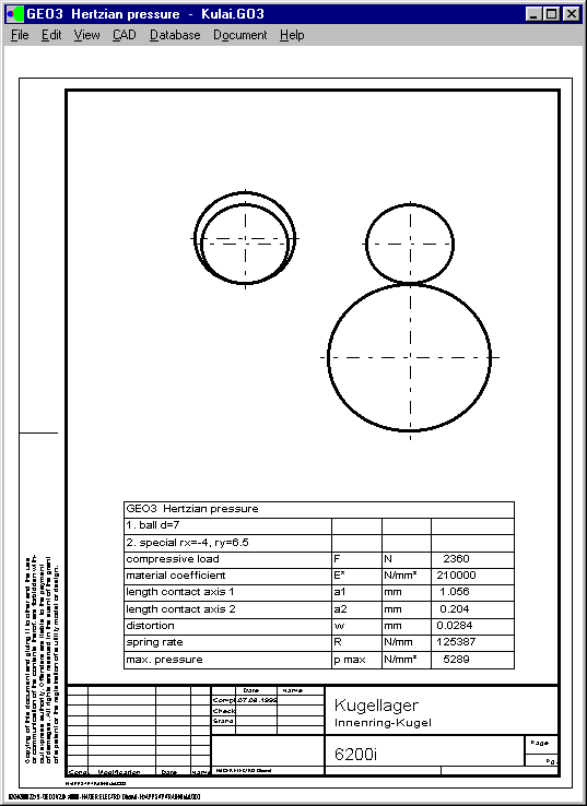
The new price of GEO3 is 400 DM (205 Euro). Thanks for improvement suggestions and calculation documents to Mr. Anderl of JAN Components and Development, Remseck, and Mr. Sobieski of RMS Consulting in St.Albert/USA and Mr. Tippel of Vögele, Mannheim.
SR1 - Permissible Pressure for High Temperature
Already the older releases of SR1 consider the reduction of tensile strength and yield point for higher temperature.
The data are input from database or calculated with an approximation formula, if not available from database.
The permissible contact pressure also reduces with higher temperature, with the same coefficient like tensile strength and yield point. The "temperature page" of the printout was modified, the reduced values are added and considered with the safety factor pperm/pmax. Thanks for the improvement suggestions to Ralph Shoberg of RS Technologies, Farmington Hills, and John Reiff of General Motors, Pontiac/USA.
        ----------------------------------------------------------------------
        Reference Temperature             T0       °C                20
        ----------------------------------------------------------------------
        Working Temperature               T        °C               100
        ----------------------------------------------------------------------
        modulus of elasticity bolt        ES       N/mm²         210000
        ----------------------------------------------------------------------
        modulus of elasticity bolt 100    ES100    N/mm²         205000
        ----------------------------------------------------------------------
        temperature coefficient           alpha TS 1/K           11.5E-6
        ----------------------------------------------------------------------
        difference length bolt            delta LS mm             0.040
        ----------------------------------------------------------------------

        CLAMPING COMPONENTS (T = 100°C)
        ----------------------------------------------------------------------
        i    alpha T     l  [mm]     l100 mm     E N/mm²     E 100
        ----------------------------------------------------------------------
         1   11.5E-6        3.000       3.003    210000      205000
        ----------------------------------------------------------------------
         2   26.0E-6       40.000      40.083     44000       38002
        ----------------------------------------------------------------------

        CLAMPING COMPONENTS (T = 100°C)
        ----------------------------------------------------------------------
        i    p perm     pperm100    p max     pmax100    delta mm/N delta 100
        ----------------------------------------------------------------------
         1      420        390        586        683     0.0562E-6  0.0576E-6
        ----------------------------------------------------------------------
         2      140        130        182        213     1.704E-6   1.973E-6
        ----------------------------------------------------------------------

        difference length clamping pieces delta LP mm             0.086
        ----------------------------------------------------------------------
        elasticity bolt                   delta St mm/N        2.924E-6
        ----------------------------------------------------------------------
        elasticity plates                 delta Pt mm/N        2.03E-6
        ----------------------------------------------------------------------
        yield point bolt                  Re       N/mm²            940
        ----------------------------------------------------------------------
        yield point bolt 100°C            Re100    N/mm²            875
        ----------------------------------------------------------------------
        dec./inc.clamping force work.temp.delta FM N              -9367
        ----------------------------------------------------------------------
        assembly prestress. force 100°C   FM 100   N              65749
        ----------------------------------------------------------------------
        tensile strength bolt             Rm       N/mm²           1040
        ----------------------------------------------------------------------
        tensile strength bolt 100°C       Rm100    N/mm²            968
SR1 - Warning den<>d
If bolted joints with English threads were calculated, sometimes the Warning "den <> d" was generated, without any reason. This was a rounding problem of SR. The warning can be ignored, with the new veersion it was eliminated.
Thanks to Theresa de la Fuente of Federal Mogul, Rugby, UK, and Nancy Saxon of Meritor Heavy Vehicles in Troy/USA for her hints.
WL1+ Shaft drawing with dimensioning
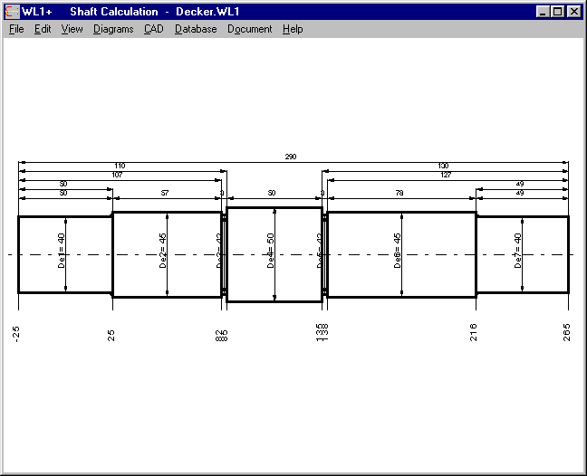
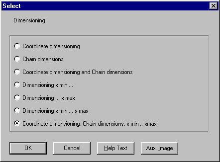
The shaft is placed at the center of the screen now, and for automatic dimensioning you have 3 new options: Dimensioning from left side (xmin), right side (xmax), or from both sides.
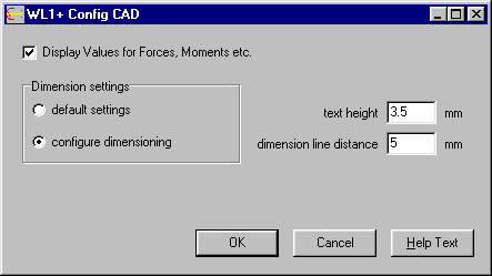
Distance of dimension lines and text height may be configured at CAD->Settings
Thanks to Mr. Canovas of Moog for his improvement suggestions .
WL1+ Edit Shaft Geometry
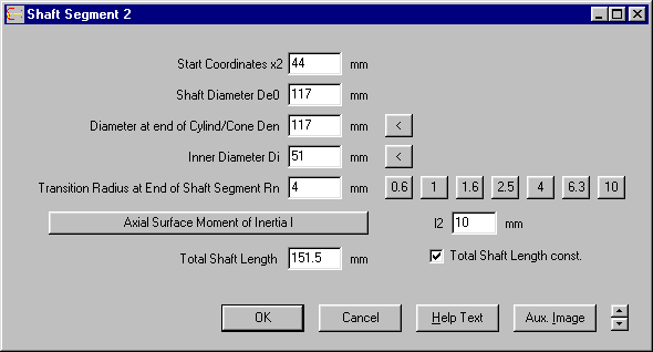
When inserting and deleting shaft segments, you can choose, if the whole shaft should be elongated/shortened, or if only the next section should be influenced. When editing a shaft section, you find a new option "Total shaft length const." If disabled, a modification of the shaft section will change shaft length and x coordinates of the other shaft segments. This option may simplify changes of the shaft geometry. Thanks to Mr. Müller, Wollbach/Germany for the improvement suggestions.
WN3 - DIN 6892
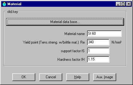
The WN3-Software was adopted to edition Nov. 98 of DIN 6892. Compared with draft of 3/96, there were no changes. New in WN3 is the possibiliy for direct input of material data for the sliding key. Until now, material data must be selected from material database.
Textattribute Settings
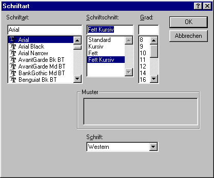
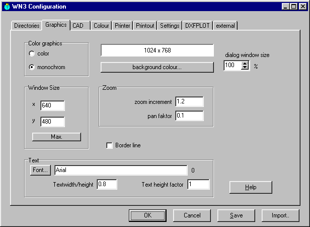
For text font at printout of text and graphics, text attributes bold, italic, bold-italic may be set. The settings are saved with the config file now.
