 | English
| Deutsch
| English
| Deutsch
FED1+, FED2+: Cost calculation
Cost calculation was improved, especially for wire diameter < 1mm. Material cost and cost for grinding are loaded from database FKWS and FKSCHL dependent from material and wire diameter. An additional database file FKPARA.DBF now includes parameters for cost calculation of heat treatment, shot blasting, machine cost, cost for 100% measure and sorting, and extra cost coefficient for buckling springs at setting length.
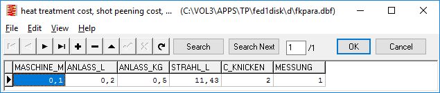
Machine cost is calculated with 0,10 Euro per meter of wire length for example (MASCHINE_M). 0,10 EUR/m = machine cost 150 EUR/60min divided by feeder speed 25 m/min. Heat treatment cost calculated with 0,20 EUR for a volume of 1 liter (ANLASS_L) or 0,50 EU per kg (ANLASS_KG). Volume for space requirement of a spring is calculated as cuboid (V = De˛ * L0). Cost of shot blasting i.e. 80 EUR for a volume of 7 liter makes 11,43 EUR/l (STRAHL_L). If spring has to be pre-set, cost is loaded from FKSETZ.DBF (load-dependent). If springs are buckling at setting length, an extra cost coefficient C_KNICKEN is applied. If springs have to be measured and sorted because of extra small tolerances, extra cost for 100% measuring and sorting (1,00 EUR of MESSUNG) and scrap are calculated.
FED7 – Insert Special Shape Spring

In FED7 you can generate pre-defined "special shapes" (conical spring, barrel spring and hourglass spring) and you can add the generated special shape to the already defined coil sections. Cause "special shape" was inserted behind and not before the selected coil section, it could not be defined as first coil section. This was corrected now, for example you can now define a cylindrical spring as one section, then add a conical spring before and behind of the cylindrical part.
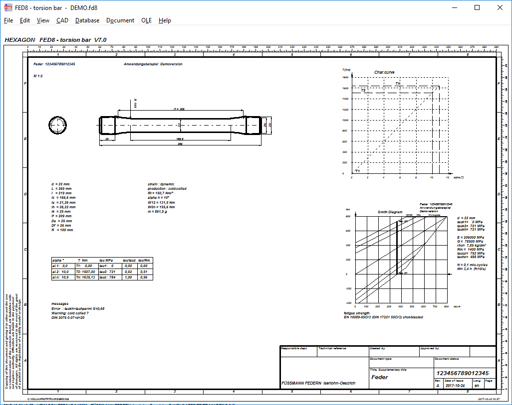
FED8: Quick4 View
New Quick4 View includes spring drawing, tables with dimensions, loads, stresses and diagrams altogether in an ISO 7200 drawing frame.
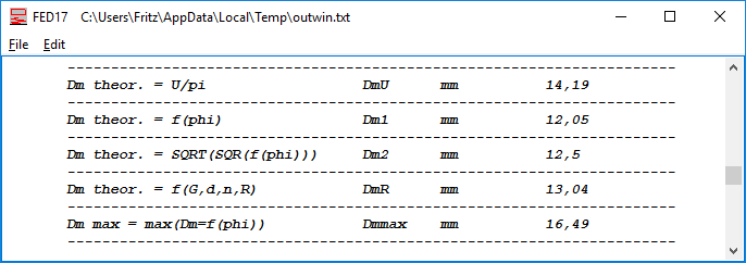
FED17 – Calculate reference diameter
Virtual diameter of a cylindrical spring with equivalent spring rate to the calculated magazine spring has been added to the printout:
DmR = ((G*d^4)/(8*n*R))^1/3
This diameter is required if you use FED7 to calculate a progressive magazine spring. Please consider that only spring load and spring rate is correct in this case. Stresses are higher and must be calculated by means of FED17.
FED10: Quick Input
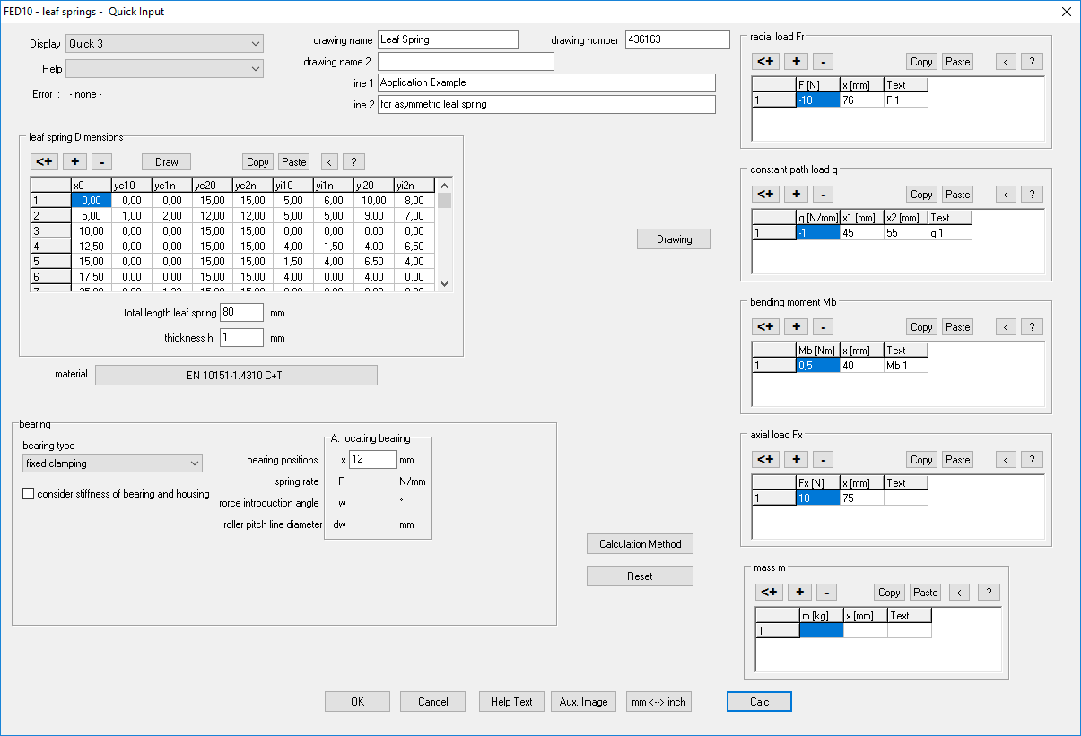
New Quick Input includes all dimensions, forces, bending moments, external mass, material and bedding altogether in one dialogue window. At "Display" you can select the desired diagram or result table in the background window, which is actualized with each click into "Calc" button.
FED10: Quick4 with bending line and stress curve
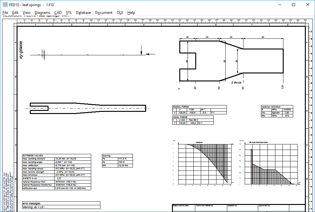
Diagrams with bending line and stress curve have been added to Quick4 graphic (if space not occupied by tables with loads). Diagrams can be drawn if sum of radial loads, axial loads, path loads, and bending moments is less than 4.
SR1/SR1+: Length of Countersunk Screw
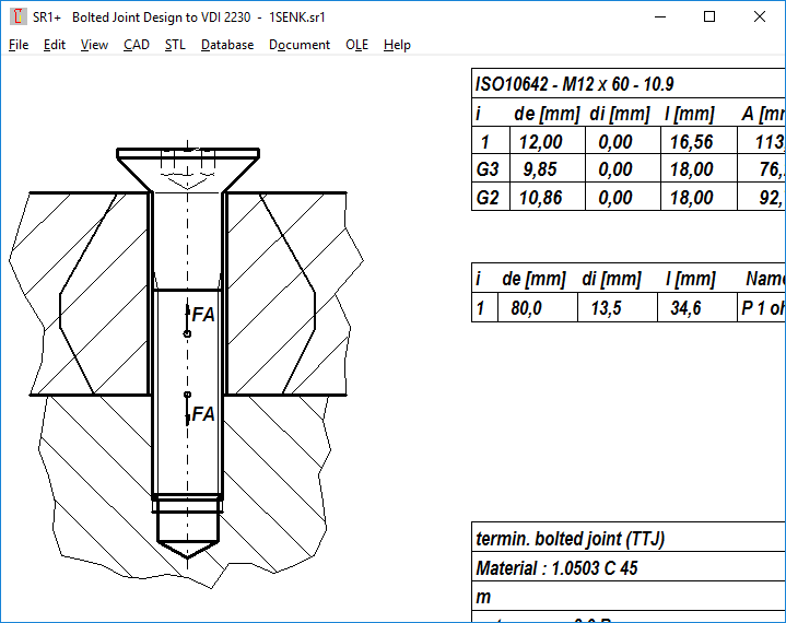
Calculation of bolted joints with countersunk screws cannot be found in VDI 2230. Deformation cone of clamping plates under countersunk screws is not researched until now. SR1 calculates countersunk screws like cylindrical head bolts. However, drawing and calculation were slightly different until now. For calculation, countersunk head was assumed to be sunk in the first clamping plate, but to be drawn so, height of the first clamping plate must be shortened by the countersunk head height. You got a warning "countersunk screw" with the suggestion to use a cylindrical head screw instead. This warning was moderated in the new version by a hint to reduce the first clamping plate by the height of the countersunk head, and that screw length of countersunk screws is measured with head and not until head. Calculation and generated drawing in SR1 are conform now, calculated thread length in nut plate and on drawing are identical. Bolt thread sections of countersunk screw are calculated without head height now. If you select a countersunk screw, input text for bolt length changes from "shaft length" into "screw length".
If you update to a new version, please check earlier calculations with countersunk screws. Maybe you have to reduce the first clamping plate by the countersunk head height.
SR1+: Quick Input: Table with clamping plates
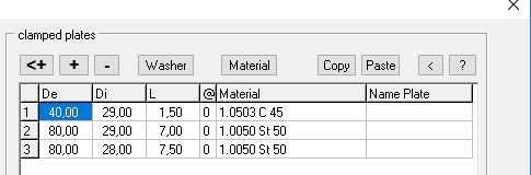
Row moving was enabled in the clamping plate table by click and hold left mouse key then pull to the desired row. If you forgot a washer, you can enter it at the end and then move it on first row.
Selection of material database and material now by double click (instead of buttons Material and <).
New "Copy" and "Paste" buttons allow exporting and importing of clamping plates by spread sheet.
SR1+: Quick Input MA +/- tol
MAnom +/- tolerance can be entered instead of MAmax and MAmin.
SR1+: Top View and Bottom View
Washers and clamping plates are drawn at "top view" and "bottom view", if not larger than 1.5*d.
WL1+: Quick Input
In Quick Input you can enter all input data (shaft dimensions, material, bedding, radial load, axial load, bending moment, path load, torque, .) in only one dialogue window now. Other new features are Copy and Paste buttons and a function to draw the shaft contour. At "Display" you can select one of 45 diagrams, drawings and result tables which will be updated after each click into the "Calc" button.

For optimal use of the new Quick Input, a large monitor with at least 1280x1024 pixel is required. Or better a higher resolution (i.e. 1920x1080) so that the graphic window with calculation results is not overlapped by the input dialogue window. For notebook, tablet or small monitors, the old input windows with separate input of shaft dimensions, material, bedding, forces, bending moment, torque etc. are still available.
LG1: Load Spectrum
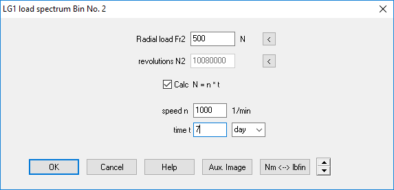
New input window for load spectrum eases input of revolutions by converting from time and speed. And maximum number of bins was increased to 255.
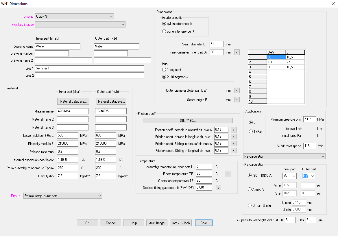
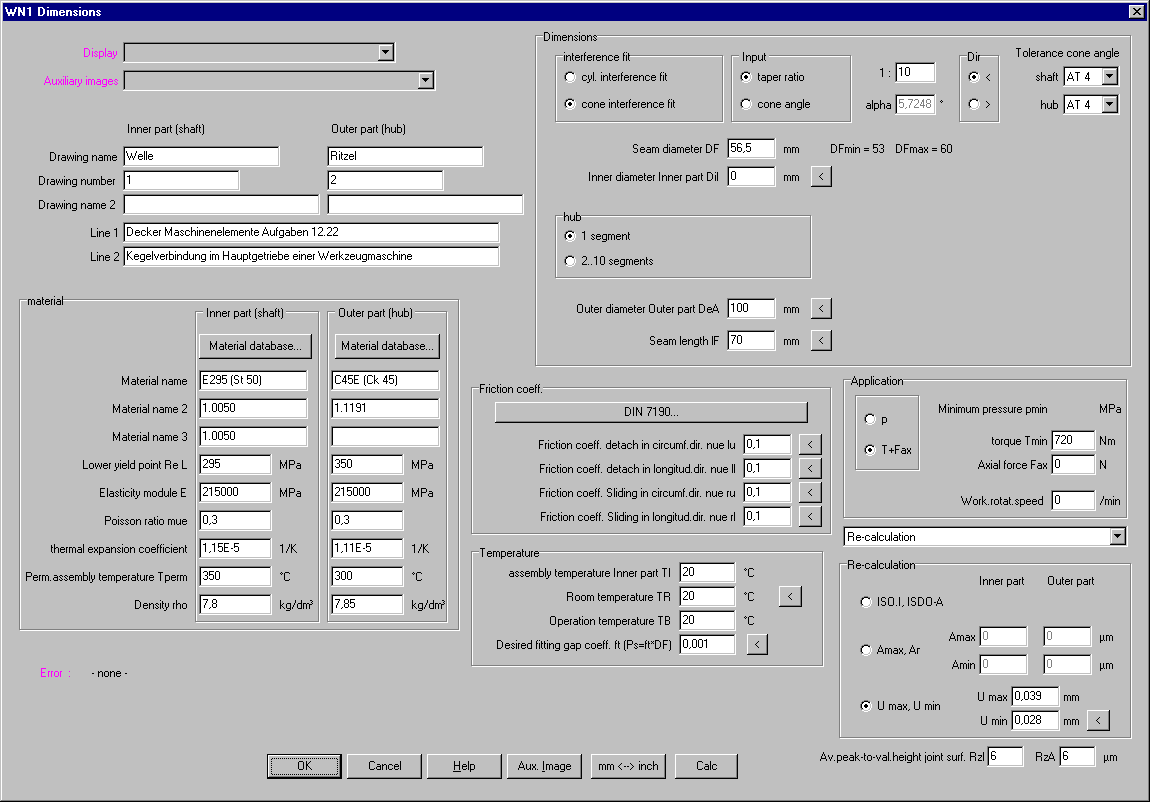
WN1: Quick Input
New Quick Input allows input of all dimensions, material, load, friction coefficients, temperatures for cylindrical or tapered interference fits or shrink fits in only one dialogue window.
WN1: Taper Interference Fit: Min and Max Values
Same as for cylindrical interference fits, min and max interference amount can be entered for taper interference fits, to calculate min and max stress, mounting force and dismantling force.
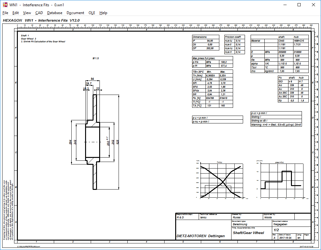
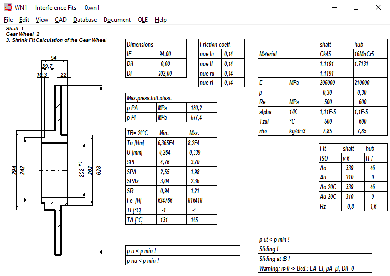
WN1: "Quick2" View and "Quick4" View
New Quick4 View includes drawing, diagrams and tables with calculation results in an ISO 7200 drawing header on one screen.
New Quick2 View provides a quick overview about calculation results and dimensions of the joint.
GEO6: New Software for Pinch Roll Overrunning Clutch
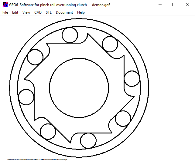
Our new software GEO6 calculates inner ring and outer ring of a pinch roll overrunning clutch.
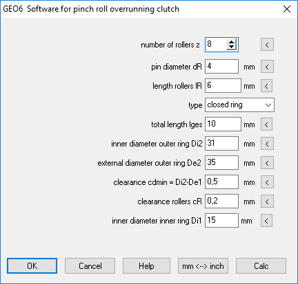
Geometry of inner ring and outer ring is generated by GEO6.
You can generate inner ring and outer ring as STL file, produce by means of your 3D printer, then build a full functioning model.