 | English
| Deutsch
SR1+: Clamping plates with oblong hole

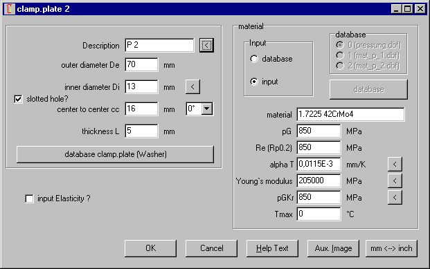
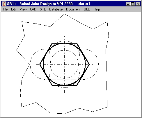
An oblong hole instead of a round hole can now be defined for the clamping plates: slot width Di and center-to-center distance cc (cc=0 is round hole).
Slot area is considered for calculation of maximum pressure (safety Sp and SpKr). Virtual diameter for round hole is used for deformation cone calculations.
A position angle of 0° or 90° can be selected to calculate overlapping slot area of neighbored clamping plates with slots crossed or in same sense. Bolt position is always assumed in center of oblong hole.
SR1+: Creep safety for FKRmin or FVmin
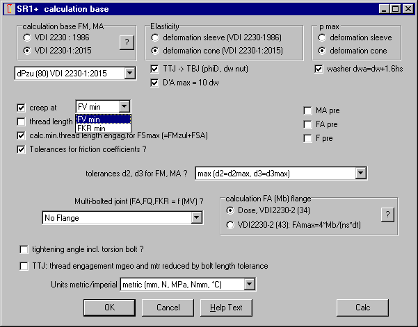
Until now, creep safety was calculated based on FKRmin. For creep safety SpKr=1, creeping until residual clamp load FKRmin was allowed. For safer calculations, better allow creeping until minimum preload FVmin. Now you can configure if safety margin SpKr will be calculated with FKRmin or FVmin. Default setting is FVmin.
SR1+: FA in drawing
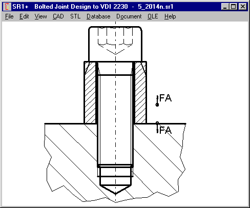
Axial load on clamping plates is plotted in the drawings now. With arrows as tensile force for FAmax > 0 and as compressive force for FAmin < 0.
SR1+: Maximum pressure in case of FA < 0 (pressure)
The case that axial load FA may be compressive instead of tensile is not really defined in VDI 2230. According to VDI 2230-1:2015, maximum pressure in working state is pBmax = (FVmax + FSAmax – deltaFVth) / Apmin (formula 191). "For joints loaded in compression (negative FA), FSAmax = 0 is to be substituted."
SR1+ calculates more precise. Outside the selected clamping plates of load introduction, maximum pressure is calculated with FSAmax, and inside FA introduction positions without FSAmax (in assembly state). In case of compressive load, outside the load introduction positions, formula according to VDI 2230 is valid (with FSA=0). But inside the FA position, compressive load share FPA must be added. pBmax = (FVmax – FPAmin – deltaFVth) / Apmin (with FPAmin < 0)
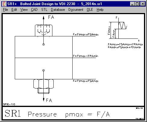
In case of FAmax > 0 and FAmin< 0 (alternating load), maximum pressure outside of FA introduction points is increased by FSAmax (as described in VDI 2230), and inside FA introduction points it is increased by -FPAmin (with FPAmin<0).
SR1: Rp0.2 instead of Re
Labels of some material database captions of yield point are not really correct: it should be "Rp0.2" instead of "Re". Titles of bolt and plate material databases have been changed from "RE" into "RP02". Data remain all the same.

ZAR3+: Contact ratio epsilon alpha
Transverse contact ratio in gear center and normal section has been added in printout for ZI worm flank type.

FED2+: Suggest buttons at input of loops
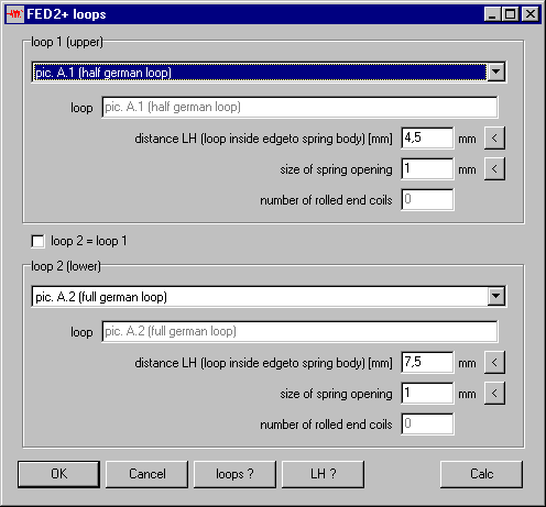
New suggest buttons "<" for input of loop distance LH and size of spring opening have been added. FED2+ suggests input dependent of selected loop type and inner coil diameter Di.
FED1+, FED2+: Period time of spring-mass-system
FED1+ and FED2+ calculates resonance frequency of spring-mass-system, if you input an external mass. Time required for one stroke (period T = 1/f) in milliseconds has been added in the printout.

FED2+: Input coiled-in prestress as load F0 or stress tau0
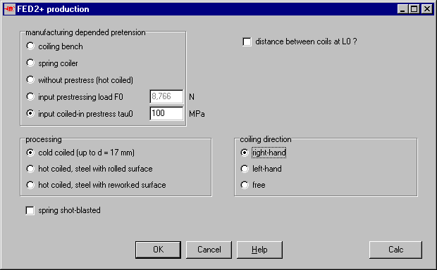
FED2+ calculates in-coiled prestress load F0 according to EN13906-2 (produced by coiling bench or spring coiler), or set to 0 (if distance between coils or hot-rolled), or input F0 directly. As additional option, you can enter prestress tau0 in MPa now.
Extension Springs in barrel shape or with conical end coils
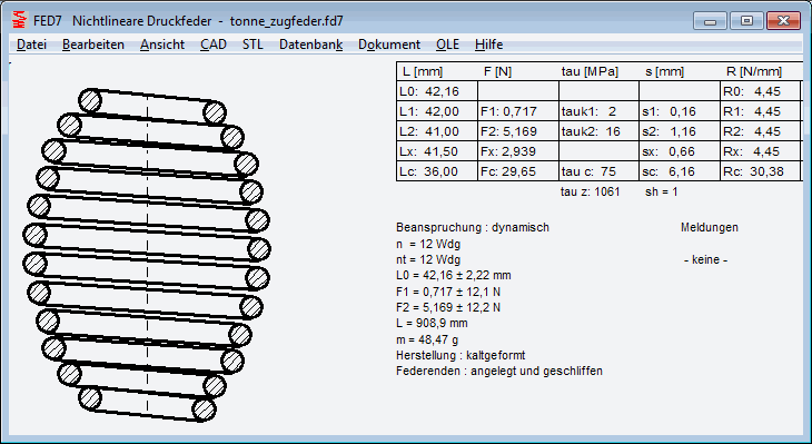
Extension springs with large coil diameter are sometimes manufactured with decreasing coil diameter at the spring ends. The loop becomes small then. This favors reduced bending stress in the loop due to a small lever arm.
Load-extension diagram of extension springs with barrel shape or conical shape is not progressive, as wrongly asserted by Gutekunst (Hanser Konstruktion 5/2017). Load-extension diagram of these extension springs may even be slightly degressive, if coils of smaller coil diameter require higher load to overpower prestress tau0. FED7 can be used to calculate spring rate of extension springs of any shape: this is the spring rate R0. R0 of extension springs, however, is the spring rate at the end of the load-extension diagram, not at start as for compression springs.
If demanded, we can make a new software for this extension spring type "FED7 for extension springs".
Spring Calculation: Comparison of material 1.4310 (302) and 1.4568 (17-7 PH)
Customers asked why 1.568 should be better than 1.4310. From material properties, this cannot be seen. But shear modul of 1.4568 (78000) is higher than G module of 1.4310 (73000).
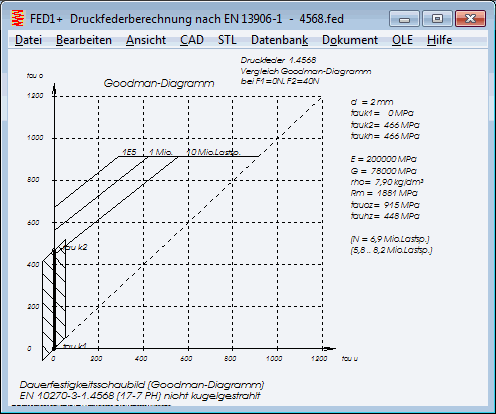
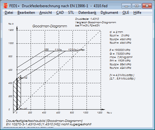
Static safety of 1.4568 or 1.4401 is not better than 1.4310. Not even fatigue strength safety is better, if pretension tauk1 is small or 0.
But 1.4568 is better in fatigue strength if pretension tauk1 is high. And 1.4568 is better if you compare fatigue strength for limited life (100,000 cycles).
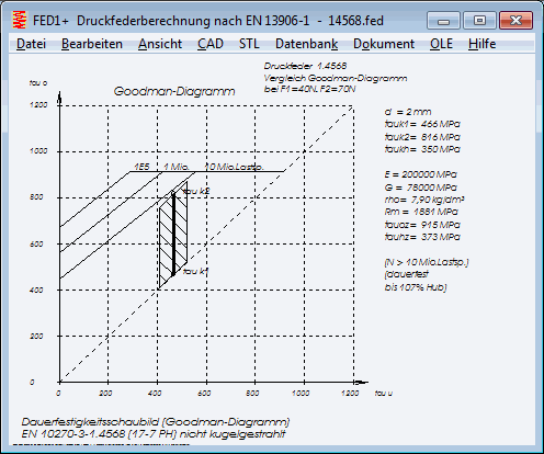

Example calculation with F1=30N and F2=70N shows the difference by means of the Goodman diagram: spring made of 1.4568 is fatigue strength safe, but spring made of 1.4310 fails after 300,000 strokes.
New EN 10270-1:2017
A new DIN EN 10270-1:2017 (Patented cold drawn unalloyed spring steel wire) was released. I found no essential changes. In table 3 with mechanical properties, minimum tensile strength for SM and DM with 14 < d <= 15mm was corrected. The value already was correct in our database file fedrmmin.dbf (1110 MPa), nothing to change.
TOL1 – Calculation of reject rate for pre-defined limits
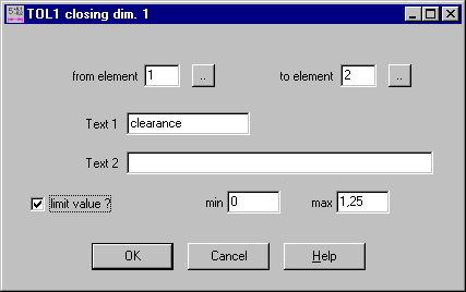
Optional input of limit min/max has been added to the input of closing dimensions. TOL1 then calculates reject rate of the dimensions that lay outside the defined limits.
Standard printout will be shorter in this case: instead of reject rates for different dimension intervals, only the reject rate of the defined interval will be printed.
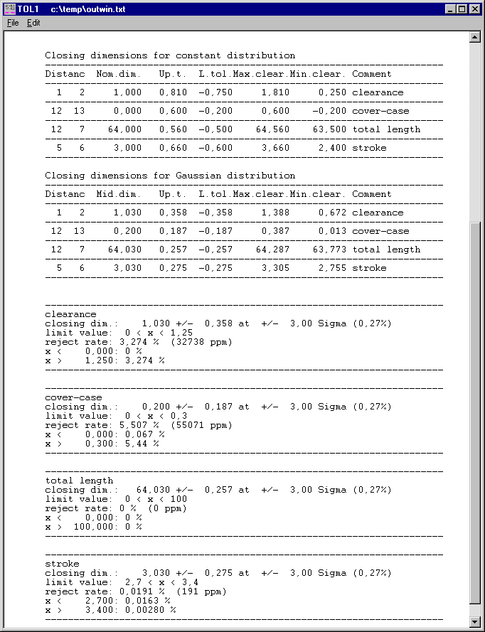
In "Gaussian Graphic", self-defined dimension limit is plotted and reject rates relative to limits are printed.
TOL2 – Calculation of reject rate for pre-defined limits
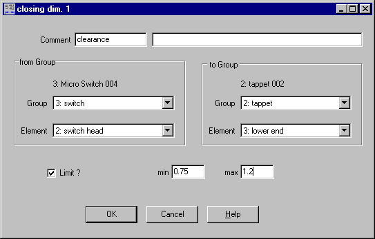
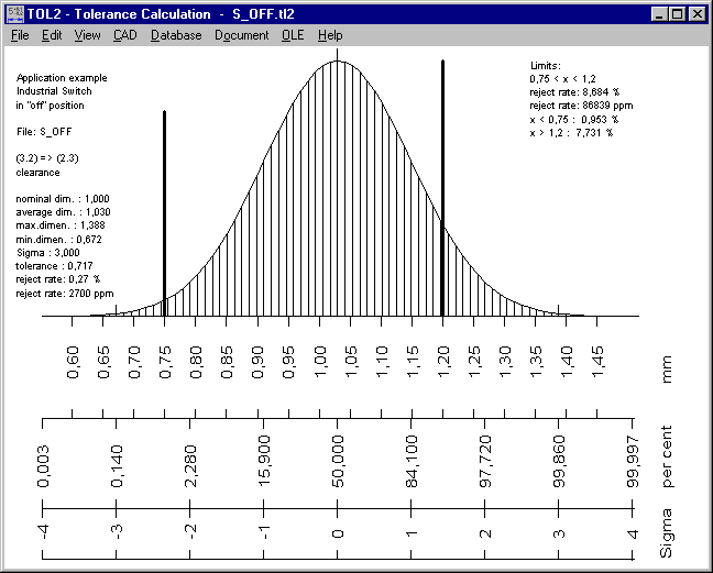
In the same way as in TOL1, you can now enter limits for each closing dimension, and TOL2 calculates reject rate. Standard printout lists reject rates for the predefined limits, and "Gaussian Graphic" plots predefined dimension limit and lists reject rates relative to limit.
30 years TOL1
In September 1987, the first HEXAGON software was released, TOL1 for tolerance calculation. Made by Fritz Ruoss engineering office, HEXAGON was founded in 1990. Followed by gear calculation software ZAR1 and spring calculation software FED1. Operating system was MS-DOS, and the programs were delivered on 360 kB floppy disc 5.25". And I was 28 years old. More 10 years, then my kids should take over HEXAGON software.