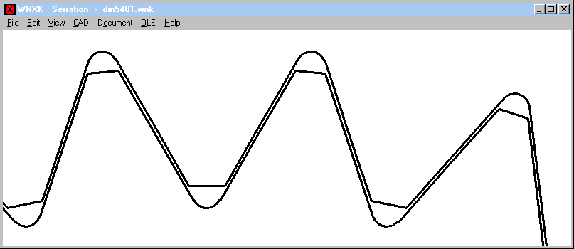

WNXK – New Software for Serration Spline Design

WNXK is similar than our WNXE software, with the difference that WNXE calculates involute splines and WNXK calculates serration splines. WNXK uses equivalent designations as for involute splines: module, tooth height coefficients, profile shift. This eases the design of self-defined serrations.
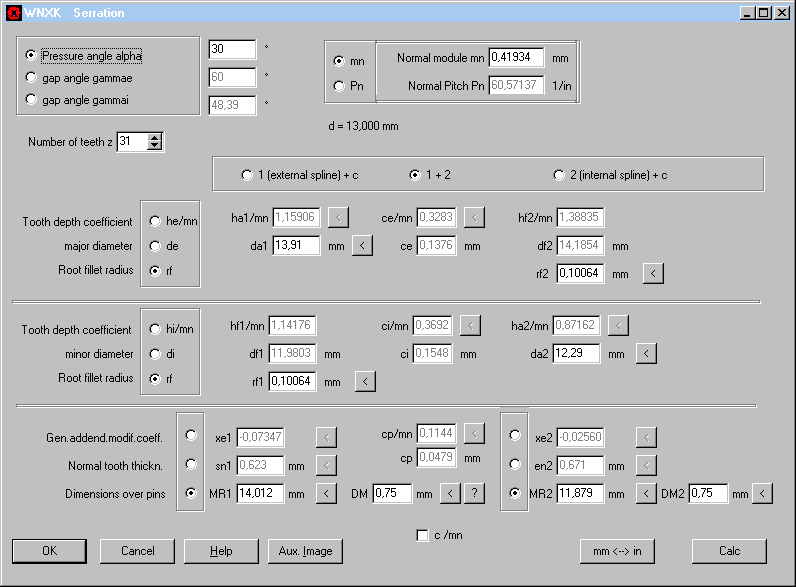
You can either input dimensions of external serration and internal serration or dimensions of external serration together with clearance and backlash, or dimensions of internal serration together with clearance and backlash.
True-scale drawings of the serration profiles can be generated as DXF or IGES file. WNXK and WNXE are useful for generating any tooth profile via wire eroding or 3D printer, and for manufacturers of broaches and gauges.
FED1+,2+,3+,5,6,7: Surface drawn/rolled/ground/shaved
Surface of cold-formed spring wire is is drawn, and surface of hot-formed springs is rolled. Surface of hot-formed springs can also be tipless ground or shaved. Nowadays, also cold-formed wire with shaved surface is available. Input of surface is just for information and has no influence on calculation results. Fatigue strength of shaved or ground wire is higher than for raw wire, but it is at yours to select another material from database with shaved surface. Oteva 70 SC (VD-SiCr) is available shaved and raw.
If you select drawn surface for hot-rolled wire or rolled or ground surface for cold-formed springs, FED software corrects your input.
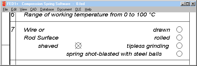
Shaved surface was not listed on printouts and drawings until now. This has been changed, shaved surface is listed and listed in the production drawings, if marked.
FED1+: Pitch m and swelling delta De of coil diameter under load
Because of queries about this theme in the last info letter, it has to be clarified: Nothing has changed in FED1+. EN 13906 was modified.
In FED1+ there are 2 calculations of coil diameter Dec: "Dec" according to EN standard, and "De" in the Quick3 and Quick4 tables, calculated by our proprietary formulas. According to this formulas, swelled diameter is calculated from wire length: D = L/(pi*nt), under consideration of lined-up end coils. These calculation allows calculation of swelled coil diameter not only for block length, but also for any spring length.

FED4,9,10,13,14,15: Round wire 1.4310 and 1.4568 added in material database
Strength properties of strip steel and round wire differ, strength values of round wire as function of wire diameter are higher than strength values of strip steel as function of strip thickness. Values of round wire have been added to the strip material database. To be used for wave springs of square or round wire section, material properties of 1.4310 (18-8) and 1.4568 (17-7 PH) spring wire according to EN 10270-2 have been added to fed9wst.dbf. If you calculate a spring made of 1.4310 or 1.4568 with square section, you can select the material with higher strength properties according to EN 10270-3 instead of EN 10151.
FED3+: E Module for FD, TD, VD (EN 10270-2)
Modulus of elasticity of FD, TD, VD (FDC, FDCrV, FDSiCr, TDC, TDVrV, TDSiCr, VDC, VDCrV, VDSiCr) according to EN 10270-2 was modified in the fedwst.dbf material database from 200,000 into 206,000 MPa. By this modification, spring moment of torsion springs in FED3 increase 3%. For compression springs, this modification has no influence, because shear module G instead of E module is used for all types of compression springs.
FED1+,2+,3+,5,6,7: Indicate required load cycles
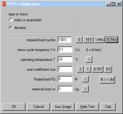
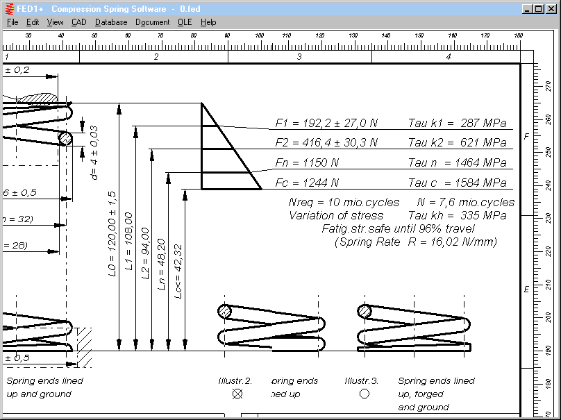
At "Edit->Application" you can now indicate number of load cycles required. If calculated number of load cycles is lower than required number of load cycles, you get an error message.
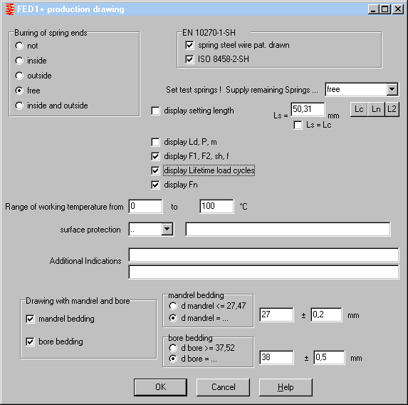
If you check "display Lifetime load cycles" at "Edit->Production drawing", required number of load cycles and calculated number of load cycles are listed in the production drawings.
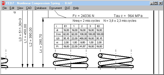
FED7: Coil Table in Production drawing with E1, E2
End coils E1 and E2 have been added to the table with coil sections.
WN8 – Tooth profile drawing improved
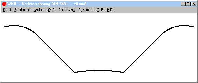
Drawing of root fillet of the internal serration spline was improved, and inside diameter of the internal serration profile is drawn as arc now (instead of straight line). At self-defined profiles with low number of teeth you can see the difference.
ZAR1+, ZAR5: Diagrams Safety and Lifetime
Diagrams for safety and life expectation caused errors and even program crash if you clicked this diagrams for zero-speed gears (torque only). The bug was fixed now. Life expectation cannot be calculated if n = 0. If you have ZAR1+ version 25.0 and ZAR5 V10.0, you can request a free update to ZAR1+ V 25.0.1 and ZAR5 V10.0.1.
ZAR1+, ZAR5: Hint/Warning if ring gear with positive profile shift
Profile shift of external gears is normally x >=0 and for internal gears x <= 0. In ZAR software, number of teeth, diameters and profile shift is negative for internal gears (ring gears) according to DIN 3960. Some other standards use always positive signs for both, external and internal gears. For number of teeth and diameters it is no problem to recognize the difference, but profile shift may be both, positive and negative. ZAR1+ and ZAR5 now give a warning, if profile shift of a ring gear is positive. To be sure that the sign is correct, compare tooth thickness or gap width or dimension between pins or balls, else set xH = - xH.
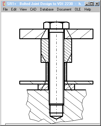
SR1+: "Washer dwa=dw+1.6hs" as option
Whether surface pressure of washers should be calculated according to formula (193) of VDI 2230-1:2015 or not, can now be configured at "Edit->Calculation method". "dwa=dw+1.6hs" defines a cone angle of ArcTan(0.8)=38.7°. SR1+ recognizes a clamping plate as washer, if thickness L < 0.5 * bore diameter Di. This formula is applied on the first clamping plate. If TBJ with nut, washer formula is applied on the last clamping plate, too.
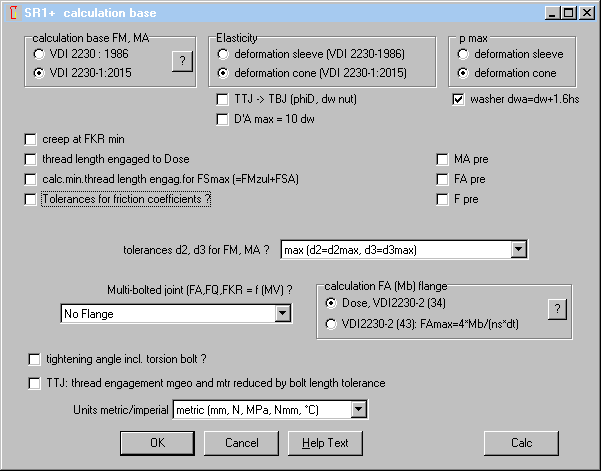
In earlier versions, option "washer dwa=dw+1.6hs" was always applied.
SR1+: Input of required residual clamping force
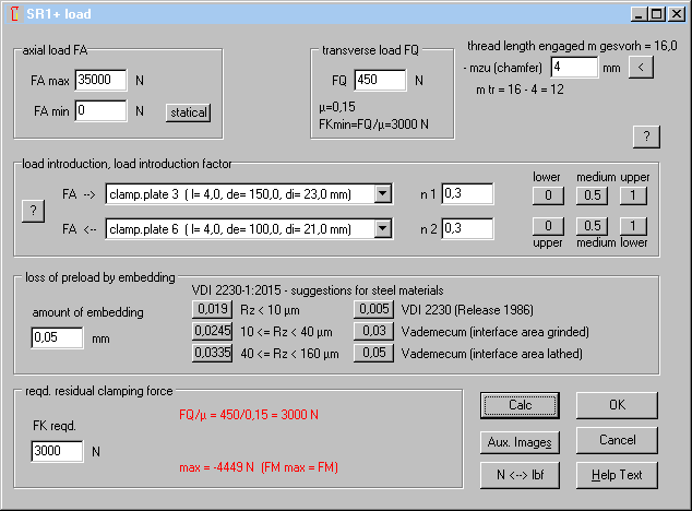
Required residual clamping force must be higher than calculated min values for radial load and eccentric load, and smaller than minimum clamp load at FAmax (FKRmin=max). If a negative value will be calculated for FKRmin (max), FA is too large and red-lighted now. If FQ/µ or FKreq,ecc. larger than max, text is printed red, and buttons disappear.
SR1+: Deformation cone dimensions if several clamping plates
D'A, the "substitutional outside diameter of the basic solid" is unclear in VDI 2230 for several clamping plates. Until now, SR1+ used D'A = Demax, the clamping plate with the largest outside diameter. This was changed now into D´A = sum(Dei*Li)/LK, so that the cone angle no longer will be extremely enlarged because of only one thin clamping sheet.
SR1+: Calculation Option "D’A max = 10 dw"
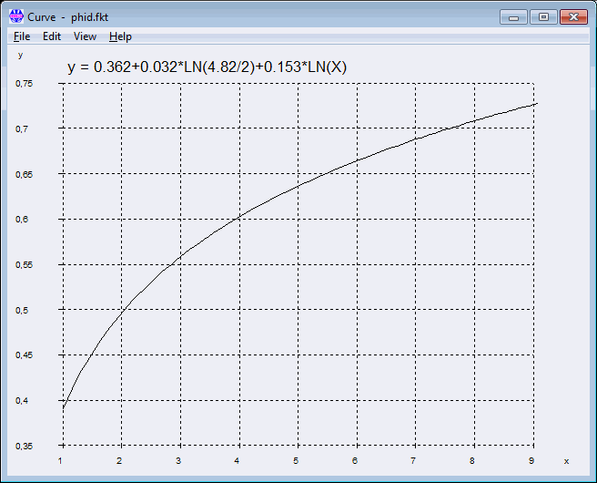
Figure 11 in VDI 2230 pretends that the curves for calculation of phiD proceeed asymptotic, and that a higher value than phiD=35° cannot be achieved. But this is not the case, cone angle increases even for y > 9. Diagram below shows the correct curve for ßL = 4,82:
There is no limit of 9 for DA´/dw, y can be much higher for bolted joints in large plates. Diagram below shows the same function until y = 100:
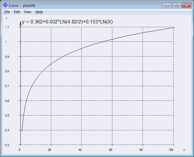
x-axis is y according to VDI 2230, and y axis is tan(phiD). For tan(phi)=1, cone angle phiD is 45°.
In SR1+, you can now limit "D´A" to a maximum of 10*dw. (Edit -> Calculation Method). This prevents the software to calculate unrealistic large cone angle phiD or phiE and limiting outside diameter "DA,Gr".
SR1+: Creep Safety SpKr
Permissible surface pressure pG according to VDI 2230-1:2015 Table A9 of most materials is higher than tensile strength and much higher than yield point. Clamping until pG may cause deformation on the clamping plate. If not immediately, then after hours or days. Because of the deformation, clamp load decreases. And surface pressure decreases, until creeping ends. In this state, one could measure the remaining clamp load (FK) and surface pressure (pGKr). SR1 clamping plate material databases got 2 additional fields: PGKR with permissible surface pressure without creeping, and TMAX with permissible operating temperature. By default, PGKR is set Rp0.2 * 0.8 (80% yield point). If operating temperature higher than TMAX (if TMAX>0), SR1 generates an error message. If TMAX set 0, it is not considered.
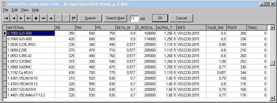
Technically, "SpKr = safety against creeping" is not correct. Creeping is allowed, but must stop at least at residual clamp load FKRmin:
SpKr = pGKr / pBKrmax with pBKrmax = FKRmin/Amin of clamping plate
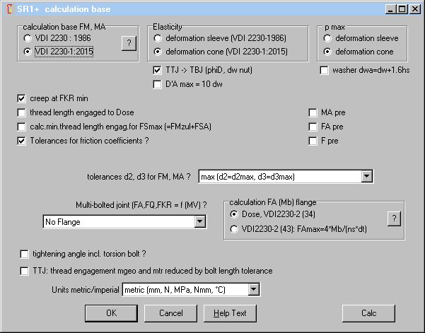
Mark "creep at FKRmin" at "Edit -> Calculation method", then "creep safety SpKr" will be calculated.
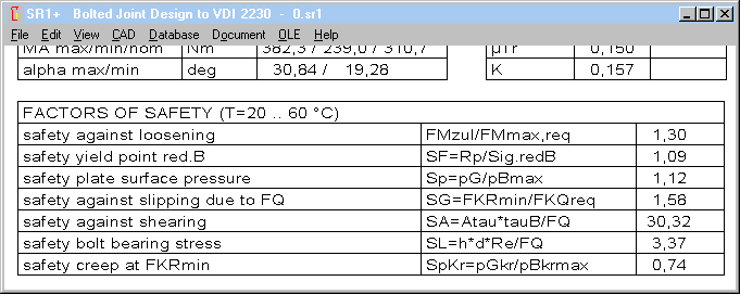
Many thanks to Mr. Sonnleitner of Siemens AG for proposals and documents. Siemens recalculates safety for creep-proof bolted joints since years. Maybe creep safety someday will be integrated into VDI 2230, and permissible surface pressure "pGKr" added in material property tables.
SR1+ Example Printout Creepage
If you mark "creep at FKRmin" at "Edit->Calculation Method", printout includes an additional table with creep stress and creep safety for each clamping plate.
       CLAMPED PLATES (DIMENSIONS)
       ======================================================================
       i     de [mm]   di [mm]    l [mm]     x[mm]   dwo [mm]  dwu [mm]
       ======================================================================
        1      40,00     22,00     32,00     32,00      28,2      40,0
       ----------------------------------------------------------------------
        2      80,00     21,00      4,00     36,00      40,0      43,6
       ----------------------------------------------------------------------
        3     150,00     23,00      4,00     40,00      43,6      39,7
       ----------------------------------------------------------------------
        4      80,00     21,00      4,00     44,00      39,7      35,9
       ----------------------------------------------------------------------
        5      80,00     23,00      4,00     48,00      35,9      32,0
       ----------------------------------------------------------------------
        6     100,00     21,00      4,00     52,00      32,0      28,2
       ----------------------------------------------------------------------

       CLAMPED PLATES (MATERIAL AND LOAD)
       ======================================================================
       i   material          E [MPa]     pG    pBmax   d.[mm/N]   aT[1/K]
       ======================================================================
        1  1.4303 X5CrNi18    200000    630     498    0,241E-6   0,0165E-3
       ----------------------------------------------------------------------
        2  1.4303 X5CrNi18    200000    630     139    0,0194E-6  0,0165E-3
       ----------------------------------------------------------------------
        3  AlMgSi0,7 F26 (     70000    172     148    0,0606E-6  0,024E-3
       ----------------------------------------------------------------------
        4  1.4303 X5CrNi18    200000    630     204    0,0259E-6  0,0165E-3
       ----------------------------------------------------------------------
        5  1.4303 X5CrNi18    200000    630     311    0,0413E-6  0,0165E-3
       ----------------------------------------------------------------------
        6  1.0577 S355J2      210000    510     437    0,0530E-6  0,0115E-3
       ----------------------------------------------------------------------

       CLAMPED PLATES (CREEP)
       ======================================================================
       i   NAME                         pGKr   pBKRmax      Spkr      Tmax
       ======================================================================
        1  Dehnhuelse                    148       194      0,76         0
       ----------------------------------------------------------------------
        2  Beilagplatte_1                148        54      2,73         0
       ----------------------------------------------------------------------
        3  Traverse                      172        58      2,99        80
       ----------------------------------------------------------------------
        4  Beilageplatte_2               148        80      1,86         0
       ----------------------------------------------------------------------
        5  Var_Beilagen                  148       121      1,22         0
       ----------------------------------------------------------------------
        6  WK-Konsole                    284       171      1,67         0
       ----------------------------------------------------------------------

pGKR: limiting creep pressure (from database)
pBKrmax: surface pressure for FKR min.
SpKr: creep safety at FKR min
dwo: outside diameter of deformation cone, upper surface of clamping plate
dwu: outside diameter of deformation cone, bottom surface of clamping plate
pG: limiting surface pressure (from database)
pBmax: surface pressure for FSmax
SR1+: Warning pmax > Re !
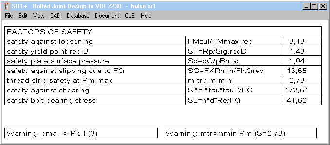
According to VDI 2230-1:2015 (table A9), permissible surface pressure pG is higher than tensile strength "Rm" and much higher than yield point "Rp0.2". This is ok for multi-axial stress condition. If the clamping plate is a thin sleeve, surface pressure higher than yield point is not allowed. SR1+ now displays a warning "pmax > Re" if deformation body is identical with geometrical dimensions and surface pressure is higher than yield point.
Example: Highest flank pressure occurs at the first clamping plate (434 Mpa) . But more problematic is the surface stress at the third clamping plate (sleeve), because pBmax = 386 Mpa is higher than Re = 340 Mpa.

All Programs: Database with new possibility to input record number directly
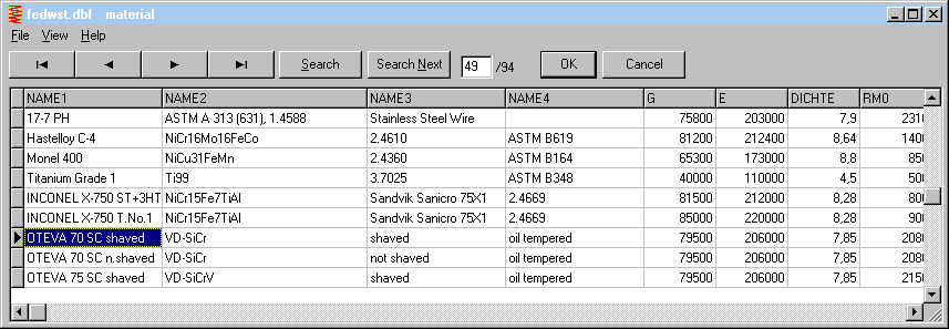
As alternative to select record via mouse or cursor keys or search function, you can enter record number directly now. Record number is displayed in an edit field now. If you input record number there, cursor jumps to the record. This accelerates input, if you have the record numbers of often used materials in mind, for example.
Software orders Update
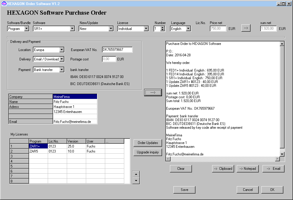
Because order form at www.hexagon.de/order_e.htm no longer generates emails, we created substitute solutions Each software got a new menu item "Help->Update" to order an update for itself. And second we developed a new "order" software for download at www.hexagon.de.
New Order software replaces online order form
Against the trend, new order software no longer runs in the "cloud", but has to be installed on the individual computer or network under Windows. The new order software not only replaces the old order form, you can also administrate your licenses there. And credit card data are coded safe by self-developed coding procedure before sent by email.
At "My Licenses" you can enter your programs with license number, current version and user information. "Order updates" button generates an update order for all of your licenses in the right text field. In the text field you can delete non-required updates, add and modify text. Then you can send text field by email, or copy via clipboard or notepad into your own order software.
Advantages of order_e.exe versus online order form order_e-htm: