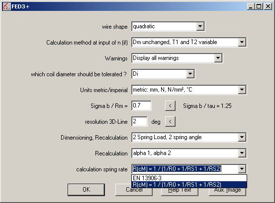
FED3+ Calculate Spring Rate with Leg Bending

EN 13906-3 describes calculation of spring angles for bended legs of torsion springs, but not the reduced spring rate because of bended legs.
In new release of FED3+, you can set an option to consider bended legs for spring rate at "Edit->Calculation Method":
Spring Rate R = 1 / (1/R0 + 1/RS1 + 1/RS2)
with
R0 = spring rate of the coil body
RS1= spring rate of clamped leg
RS2= spring rate of moved leg

FED3+ Influence of Modifications in Material Database
If you changed material database, or replaced fedwst.dbf file with updated values, results of earlier calculations may differ. When you open a file, data from current material database are used for calculation. Modifications in strength data result in changes of stresses and safety margins.
In 2008, some materials had been updated with material data according to EN standards (see HEXAGON info letters 108 and 110). For spring wire 1.4310, E modulus was changed from 195000 into 190000, and for wire 1.4401 from 190000 into 185000. If you open old calculations with springs of 1.4310 or 1.4401, software recalculates number of coils. On a helical compression spring, you would hardly notice the changes. In case of a torsion spring, however, even small change in coils results in large changes of the leg angles delta, so that the torsion spring drawing seems completely different on a glance. If, for example, number of coils changed from 3.5 into 3.4, leg angles enlarge 36° (i.e. delta0 from 180° into 216°). To adapt old calculations with new material data, you can change back delta2 at "Edit->Dimensioning", then save file. If torque must remain unchanged, you have to adopt coil diameter instead.
Alternative (not recommended) method: Undo changes in material database at "Database->fedwst.dbf", field "E". Or when updating your software, do not replace database (dbf) files.
WN1 – Stress Distribution Diagram
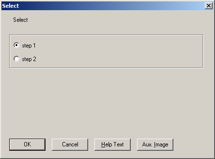
For stepped hubs, no stress diagram was provided until now. New release of WN1 lets you select the step to get a stress diagram for each segment.

WN1 - Flow of Torque and Pressure in Stepped Hubs
WN1 calculates torque and pressure of stepped hubs separate for each segment. New release of WN1 provides diagrams with min. transferable torque and pressure for the hub segments.
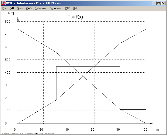
Diagram T = f(x) also includes curve for flow of transferable torque along the hub length (started at begin and end of hub).
WN1- Deformation
As a result of pressing or shrinking process, hub will be enlarged and shaft will be compressed. Deformation factors and extension is listed in the printout. New release of WN1 also lists the extended outside diameter of the hub, and for hollow shafts the reduced inner diameter after the pressure process as well. A table of the deformation data also has been added to Quick view (for non-stepped hubs only).
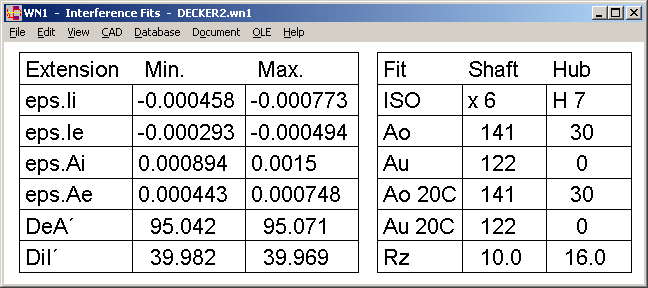
WN1 - Quick3 View
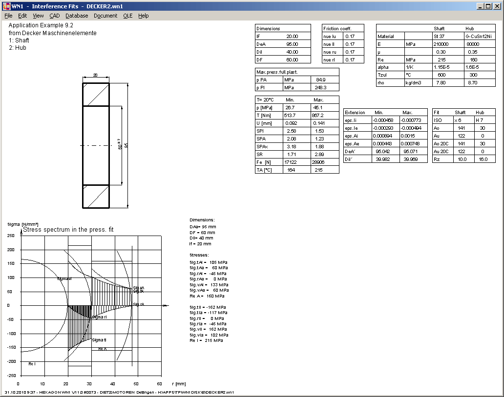
New Quick 3 view includes old Quick view tables together with a hub drawing, and for stepped hubs the diagrams p=f(x) and T=f(x), or for non-stepped hubs the stress distribution diagram.

ZAR1+ Load Spectrum
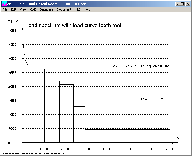
ZAR1+ calculates equivalent torque and application coefficients KAF and KAH from load spectrum. According to DIN 3990-T6, load intervals are considered only if Ti > Tn/2 (torque must be higher than 50% of nominal torque). Until now, ZAR1+ checked only the load interval of lowest torque (no-load operation) for this criteria. New release of ZAR1+ checks and filters all load intervals for Ti>Tn/2.
ZAR1+ Tooth Shape in Normal Section
Profile drawings of helical gears are always drawn in transverse section. Only the reference profile (tool profile) is in normal section. In the tooth shape drawings, however, shape of tool profile is drawn in transverse section as well.
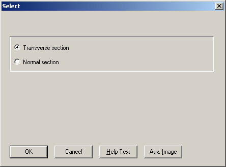
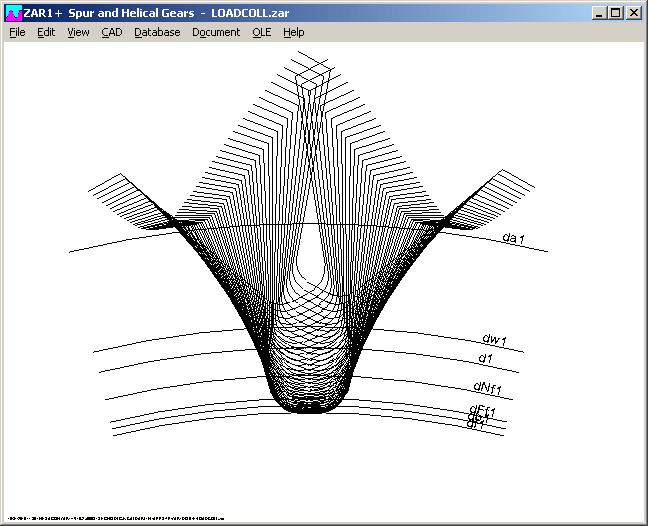
At "CAD -> Tooth Profile.. -> Tooth gap (tooth shape and involute)", new option to draw tooth shapes alternatively in normal section (without transverse involute curve) has been added.