
 | Deutsch
| VDI2230-1:2014
New release of VDI 2230 was issued in November 2015. It is approximately identical with the release of December 2014. Changes are not described. I found some mistakes corrected:
pg. 36 (R9): Calculation according to equation (186)
pg. 102: equation (211): "RS3" changed in "RS" .
pg. 102: equation (213) .. + 1.2 * P changed in 2 * P.
pg. 122: table A9: 42CrMo4: pG = 300 N/mm² changed in 1300 N/mm².
pg. 122: table A9: GJL-250 mat.no. 0.6020 changed in 0.6025.
pg. 132: example B1: R2: FKerf = 103 N changed in in 10³ N.
pg. 134: example B1: R8: FSmax = 64 194 N changed in 66 194 N.
pg. 155: example B4: R8: .. "with equation (178)" changed in .. "with equation (163)".
pg. 170: example B5: R11: mvorheff changed in meffvorh.
VDI 2230-1:2015: remaining mistakes and notes
Pg. 11: I, IB, Ibers, IBT ..
Translation error: Flächenträgheitsmoment = area moment of inertia (not moment of gyration)
Pg. 35 (R8/1):
Cit.: FSmax = FMzul + phi en * FA max - deltaFVth
Better: FSmax = max (FMzul, FVmax + FSAmax - deltaFVth)
Maximum load in operational mode is FSmax = FVmax + FSAmax - deltaFVth
Maximum load in assembly mode is FSmax = FMzul.
Pg. 36 (R9/1):
Stress area of Sigma a is A0 instead of AS (at least for necked-down bolts and hollow bolts).
Pg. 37 (R10/3): pmax = FMTab/Apmin *1.4
Equation (R10/3) for yield-controlled tightening only.
Yield point scatter is +15% for 12.9 and 10.9 bolts only, and +30% for 8.8 and lower.
For 12.9 and 10.9 bolts, a factor of 1.25 would be sufficient.
Pg. 37 (R12/2): FKQerf = FQmax / (qF*µTmin) + MYmax / (qM*ra*µTmin)
Number of interfaces makes no difference in clamp load.
FKQerf = FQmax/µTmin
Rather the clamp load should be increased due to the larger distance between the radial loads, causing a bending load FQ*distance.
Pg. 50, 51, 52
Bending body must be calculated from the real geometry (prismatic), not from a virtual deformation body (cylinder and cone) of the bolted joint.
Pg. 67 Equation (98): phim* = n * ...
Load introduction coefficient of axial load FA must not be used with MB.
Pg. 69 Table 4
Cit.: "distance v is always positive"
Then distance u is always positive, too. Because u + v = cT (length of interface area).
How if alternating load FA? Load case I for FAmax, and load case IV for FAmin? With commutation of u and v for each load cycle? Why must point U always lie at the "side of the interface which is at risk of opening"?
Table 4 with sign rules is unnecessary. If bolt axis and FA lay on the same side of the center of gravity axis of the interface area, ssym is positive. If bolt axis S and FA lay opposite to the gravity axis 0-0, ssym is negative.
Pg.88, Figure 33
A limitation line at tensile strength (FM,Rm) would be helpful. For bolts 12.9 or 10.9, FM,Rm would be less than 1.4*FMTab.
Load-deformation curves in figure 33 apply for quality 8.8 or worse.
Pg. 88 (149)
Cit.: SigmaZ = 1/A0*(FMzul + FSAmax – delta FVth) + MSbmax/Wb
For eccentric load, bending stress by MB has to be added. And for operating state, FMzul can be replaced by FVmax.
Centric: SigmaZ = max(FMzul/A0, 1/A0*(FVmax + FSAmax – delta FVth)
Eccentric: SigmaZ = max(FMzul/A0, 1/A0*(FVmax – delta FVth) + SigmaSAb
Remark: FSAmax/A0 and Msbmax/Wb is included in SigmaSab. And equation (186) has to be modified, so that external bending moments MB are considered., see Pg.95.
Pg. 88: (150):
Equation (150) is redundant, equation (149) is sufficient
Pg. 90,91: FV1
Clamp Load FV1 calculated with equation (161) is higher than permissible assembly preload FMzul.
Pg. 95 (186)
Bending moment MB is not considered in Sigma Sab calculation.
And stress in the weakest area (with A0 and Wb0 instead of AS and WS) should be calculated (concerns hollow bolts and waisted bolts)
Equation (186) with bending moment FA*a and bending moment MB should be:
Sigma Sab = phien*FA/A0 + ßP/ßS*(FA*a – FA*ssym*phien + MB(1-sign(ssym)phim)/Wb0
Pg. 96 (187, 188, 189)
Equations (187), (188), (189) are redundant.
Pg.99: Equation (201)
C1 is undefined for s/d < 1.4 and for s/d=1.9
Pg.99: Equation (202)
C3 = 0.728 +1.769 RS –2.896 RS^2 +1.296 RS^3

Function has a maximum at 0.429, not at 0.4. And a minimum at RS=1.061
Scope for RS should be 0.43 .. 1
And for RS<=0.43: C3=1.055 (not RS=0.4).
Pg. 102: Equation (211)
Polynomial function for C2 is not continuous.
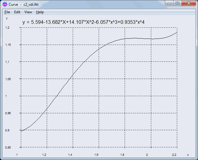
Pg. 103: Equation (217)
FQres = FQmax/qF + Mymax/(qM*ra) with qF = number of interfaces.
Radial load does not decrease over interfaces.
Pg. 130: Annex B Calculation Examples
Module of elasticity (E) of bolt materials 8.8, 10.9 and 12.9 is 210000 MPa at 20°C. However, in all of the calculation examples, E = 205000 MPa was used.
Pg. 132: Example B1: R3:
Cit.: "Due to the relatively small differences between the diameter of the head bearing surface (dw = 17.23 mm) and the bearing surface diameter in the interface (DSt=25 mm) ... as a simplification a mean bearing diameter surface can be used in calculation."
Comment: The "relative small difference" is "only" 45 % (25-17,23)/17,23 * 100%.
The result of the precise calculation is deltaP = 0.422E-6 mm/N and phiK = 0.178.
Bearing diameter dw of the piston rod should also consider the chamfer, so that dw may be about 23 mm.
Pg. 136: Example B1: R11:
TauBM/RmM=0.657, tauBS/RmS=0.62, -> RS=0.985.
If calculated with thread tolerances, RS>1 (1.01), this means critical bolt thread.
Pg. 138: Example B2: R0:
Rough determination step D: column 3 of table A7 at 100 000 N is not M16, but M18 for strength grade 10.9.
Pg. 143: Beispiel B3:
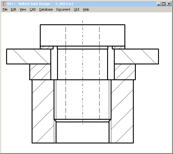
Drawing: Minimum bolt diameter should be d0. But in the drawing, minimum bolt diameter is smaller than d0. Or the drawing is correct, and error is in dimensioning of d0. I assume that d0 is minimum external bolt diameter, and the first section of the bolt (dimensioned with d0) is 27 mm.
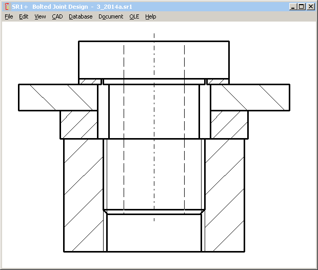
Pg.142,143: Example B3:
If bolt head dw=36 mm and nut dw=48 mm (relative small difference 33%), bolted joint has to be calculated as TBJ, instead of TTJ (same as example B1).
Pg.144: Example B3:
delta i = (l1+l2+l3)/ES/(A0-ABohrung)
A0 wrong, because of different diameters d1,d2,d3
Pg.147 Example B3: R10 pressure
Ap=pi/4*(36²-29²) = 357 mm²
pMmax = 140300N/357mm² = 393 N/mm²
Sp = 1.8
Pg.147 Example B3: R10 Pressure
False: Table A9: pG=900 N/mm²
Right: Table A9: pG=1300 N/mm² for 16MnCr5
Pg.147: Example B3: R11 Length of engagement
Equation used for calculation of RS is valid for equal shear stress coefficients of bolt material and nut material only. But tauBS/Rm of 8.8 is 0.65 and tauBM/Rm of 16MnCr5 is 0.85 according to VDI2230-1:2014 tables. Calculated RS is then 2.0, and not 1.52.
Pg.148: Example B3: R11 Length of engagement
Cit.: "while this applies to the hollow bolt: Rmmax*AS = FMzul"
What? Rmmax*AS = FMzul ? Why?
For hollow bolts, use A0 instead of AS, but not FMzul.
Rmmax * A0 = 830 N/mm² * 1.2 * 251 mm² = 250 kN
That is approx. twice as FM zul.
Calculated length of engagement is then 4.85 mm only, plus mzu=2.4mm
Here the correct results:
meffmin = 8,0mm (instead of 4,8mm) with Rmmax*A0=250Nm and C2=1.16 from RS=2.0
mgesmin = meffmin + mzu = 8 + 1.2*2 = 10.4 mm
Why is mzu 1.2 P only? Normally, it is 2.0 P.
Pg. 149: Example B4:
Faulty design: fitting surface of the bolt does not meet interface between connecting rod and connecting rod bearing cap. Bolt must be assembled upside down (bolt head at connecting rod side) or bolt dimensions have to be modified.

Apart from that, I would recommend a fine thread for this application.
Pg.149: Example B4: Initial conditions
Cit: "Cq 45 heat treated to a tensile strength of 900 N/mm²"
Cq45 cannot be heat-treated to 900 N/mm². +QT: 700-850 N/mm² for t<8mm
Pg.150: Example B4: R1: Determining the tightening factor alphaA
Cit.: The bolt is tightened using the angle-controlled tightening technique.
Wrong: According to table A8, the tightening factor alphaA=1.
Right: According to table A8, the tightening factor alphaA is between 1.2 and 1.4.
alphaA=1 is a theoretical ideal case without scatter nor friction tolerance.
Pg. 152: Example B4: R2
The determination of the of the total area produces Ages = 12*25 = 300 mm², not 272mm².
Or was it calculated with the precise interface section? If yes, these values also should be used for IBT.
But IBT = b*cT³ = 3600 mm^4

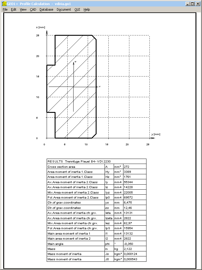
Calculated by means of GEO1+ with Ages=272mm²: IBT = 2822 mm^4
Pg. 153: Example B4: R3: Elastic resilience deltaP
Bearing diameter of bolt and nut is different (12.3 mm and 11.6 mm), therefore the deformation cones are different.
deltaP= 1.407E-6 mm/N
Pg. 153: Example B4: Bending body
Area moment of inertia IBers is calculated from a prismatic bending body (correct) jointed with the conical cones of the bolted joint deformation zone (false). Vice versa, cross section of the bending body has its minimum in the interface, and even increases in direction towards bolt head and nut.
Pg.155: Example B4: R8:
FV1 = 31 467 N
Then the clamp load following initial loading is higher than permissible assembly clamp load FMzul with 26 444 N!
Pg.156: Example B4: R8:
Cit.: The BJ satisfies the requirements.
But working stress sigma red,B should be calculated in R8, and not the remaining clamp load!
Sigma0 = FMzul/A0 + SigmaSabmax = 26442 / 26.6 + 61 = 1055 N/mm²
taumax = MG/Wp = 363 N/mm²
Sigma red,B = 1102 N/mm² (with ktau=0.5)
SF = Rp0.2 / Sigma red,B = 1100 / 1102 = 0.998
Pg. 157: Example B4: R9:
SigmaSAbo: For maximum bending stress in the weakest cross-section, dS = 6.827 mm must be replaced by dT= 5.82 mm, and AS must be replaced with A0=pi/4*dT².
Sigma SAbo is then 62 N/mm²
Pg. 157/158: Example B4: R10:
Concerning factor 1.4 for pmax, see remark pg. 37
Concerning limiting surface pressure of Cq45, see remark pg. 149
Pg. 161: Example B5: R2:
Cit.: The material region until the cylinder center is to be considered..
Thus: D’A,I = 2*rs = DST = 175 mm
Comment: deformation of bolted joint is not influenced by material zone in cylinder center. Distance to external diameter is 17.5 mm, and to the next bolt hole 14.65 mm. Thus, "D’A,I" may be about 40 mm.
Pg. 162: Example B5:
Recalculation: ssym is +1.98 mm, and not –1.7 mm. Even in figure B7, ssym is positive.
"Check for the sign rule according to table 4" corresponds to case I, and not to case III.
ssym is the distance between center of gravity axis and bolt axis. GEO1+ software may be used to calculate center of gravity and ssym.
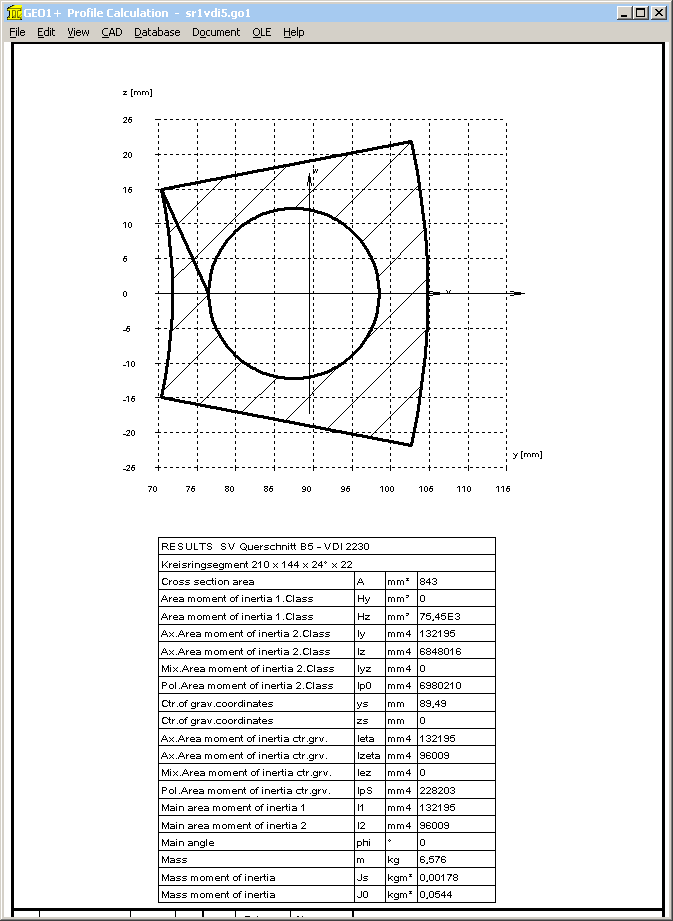
With coordinates of interface area are ri=72mm, re=105mm, alpha = 24°, rS=87.5mm and dh=22mm, GEO1+ calculates ys=89.48 mm. Thus ssym = ys – rS = 89.48-87.5 = 1.98 mm, u = ys – ri = 89.48-72=17.48 mm, and v = re - ys = 15.48 mm.
Area moment of inertia at w axis is Izeta= IBT = 95985 mm^4.
Pg. 163
R3: deltaM is not 0.104E-6, but 0.102E-6 mm/N
Pg. 164
lers = 5,93E-8*205000*pi/64*16.93^4 is 49.0, not 48.7 mm
Pg. 168: R8
Cit.: sigma zmax = FSmax/AS = 780.3 N/mm²
Comment: Bending stress by eccentric load not considered
Correct: Sigma zmax = FMzul / As + Sigma Sab = 190000/245 + 35,6 = 811 N/mm²
Sigma red,B = 841 N/mm²
SF = 1,12
Comment: Calculation with FVmax instead of FMzul results in sigma zmax = 786 N/mm²
Pg. 170: Example B5: R11:
RS must be calculated with tauM/tauS instead of RmM/RmS, because tauBM/RmM=0.8 and tauBS/RmS=0.62 are different. RS=0.79 is correct
Pg. 170: Example B5: R11:
Insufficient length of engagement: hexagon socket head bolt M20x60 allows chamfer and non-bearing thread on a length of u <= 2P according to EN ISO 4762:2004. Together with 1*P for the inner thread, length supplement to the length of engagement is then "mzu" = 3*P. With meffvorh = mvorh – 3*P = 17,5mm follows that: meffvorh < meff.
This means that a detailed calculation as per section 5.5.5 is required.
The calculated value for nominal diameter of d, D, D2 and d2: meff = 18.2mm. Results with thread allowance of internal thread and bolt:
6H/6h: meffmin=18.6 mm
6H/6g: meffmin=18.9 mm
6H/6e: meffmin=19.2 mm
What is missing in VDI 2230-1:2015 ?
A table of bolt materials with E module, yield point, tensile strength, tolerance of yield point and tensile strength, shear strength and temperature coefficients, elongation after fracture.
05.12.2015 Fritz Ruoss